 Ken Yap
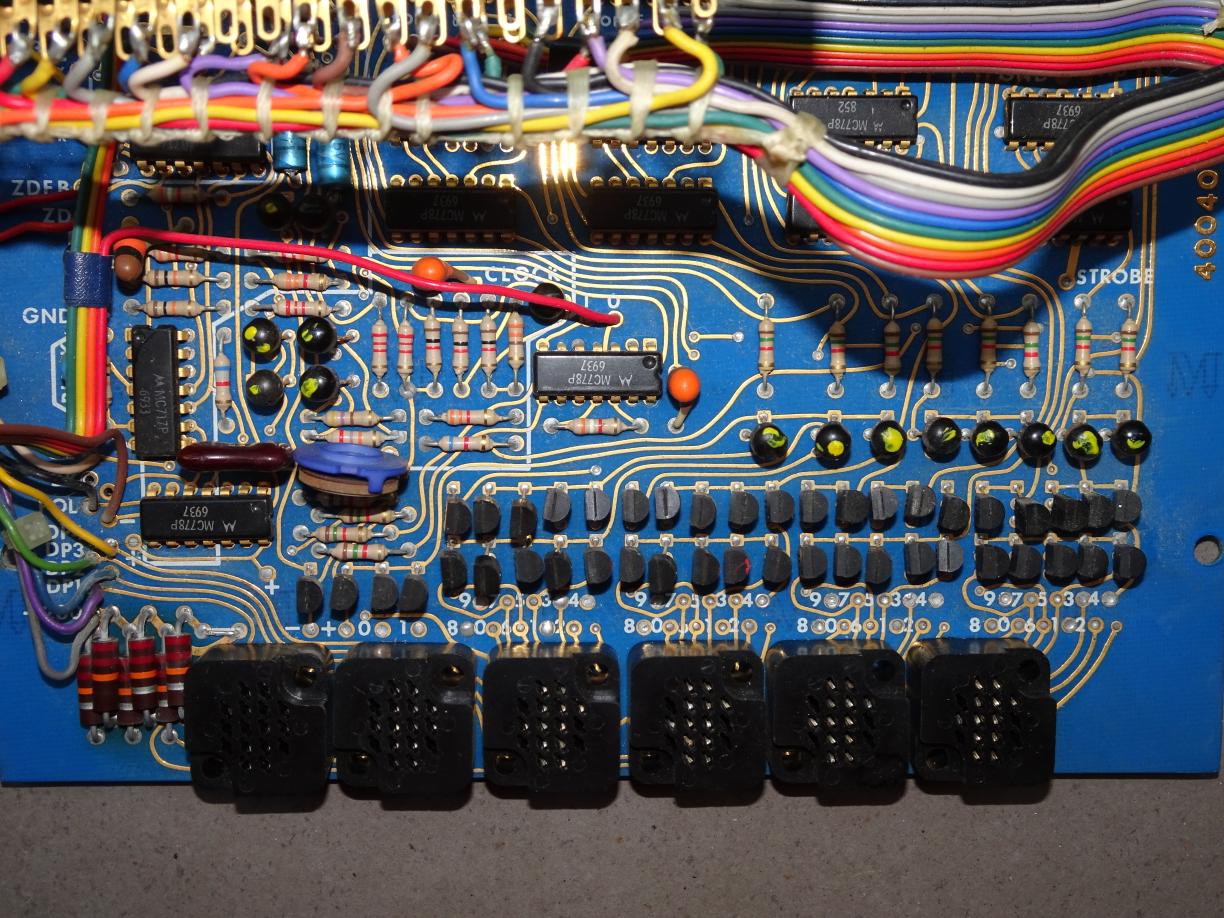
So, time to identify what I have to work with.
First the nixies. I had forgotten but there are only 5 numeric nixies, the rightmost 5, which are type ZM1000. The leftmost nixie is a symbol nixie ZM1001 which can display X, Y, Z, +, - and the sine wave symbol. Information on them is readily available. They were made by Valvo in Europe. Pretty standard specifications: 14mm tall characters, strike voltage of 170V, sustain voltage not mentioned but from my experience around 145-150V, 2.5mA max current. What's notable is the Eurogrid base which you can see from the sockets in the photo. Those sockets are probably very expensive or even unobtainium, so all the more reason to use the board as is. I have unplugged the nixies to protect them while I examine the board.
Moreover you can see from the silkscreen legend that the leftmost digit displays only 0 or 1, the other cathodes are not wired up. Thus the meter is what we would nowadays call a 20000 count meter. The decimal point is selected by wire so it would be in one position only. That makes sense with the max temperature of 1600°F. Now it comes back to me that there was a static neon indicator that displayed °F to the right of the nixies in the box that I had removed.
The symbol nixie is wired to display only + or -. All this makes sense, but it means that unless I undertake more radical modifications I have only 4 usable digits. I suppose it could be a 12-hour clock, but what should the 5th digit display?
Moving on, it's not true that all the chips are the MC778 (dual D flip-flop). There are a few MC717s on the board, which is a quad 2-input NOR gate. In RTL, NOR is the basic gate, compare with TTL where NAND is the basic gate, e.g. the 7400.
I'm getting ahead of myself, but I found that the GND and Vcc pins were 4 and 11 respectively, i.e. in the middle of each side. According to the 1975 Don Lancaster book RTL Cookbook, this is the standard for RTL chips in the plastic P package. I have provided a link on archive.org to that book. We will see more from that book, but I don't want to get ahead of myself. This means the datasheet I presented before has the wrong pins, because it's for a different package. After some searching I found the correct pinout in a 1976 D.A.T.A book.
The driver transistors are 2N4409, which is specifically intended for driving neon displays, with a min breakdown voltage of 50V. That's sufficient, the transistor has only to hold off the difference between the supply voltage and strike voltage, which is 200V - 170V = 30V.
The bundle of 6 higher wattage resistors on the far left are the anode current limiting resistors which measured at ~22kΩ. So the operating current is (200V-145V)/22kΩ = 2.5mA. Sounds right.
There are 8 other transistors on the top right, which are 2N5134. Their purpose will be revealed in the next log.
Discussions
Become a Hackaday.io Member
Create an account to leave a comment. Already have an account? Log In.