 Ken Yap
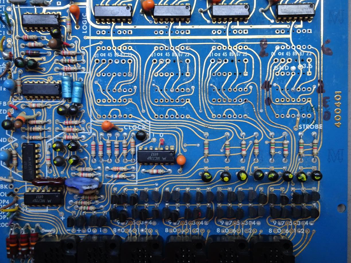
As mentioned in the log Decoding the decoders, a biquinary scheme is used to drive the cathodes. Briefly, there are 10 HV switching transistors, but they are arranged in 2 banks of 5, with a low side transistor switch to select the odd or even bank. This means that 7 lines are used to select 1 of 10. You can see the 4 banks of 10 above the sockets, and the 4 pairs of bank selector transistors above them. These were driven from the flip-flops. I will be driving them from my #3 line to 32 line output expander board.
I removed the flip-flops so there are no stray connections to the bases of the transistors. Even though the old RTL logic remaining on the board will not be powered, there might be stray paths to ground. Desoldering the flip-flop ICs wasn't as difficult as I feared. I needed only a normal conical tip soldering iron and a vacuum solder sucker. I didn't want to escalate to the heat gun because that can damage the board and components. In the end 10 out of the 12 ICs came out undamaged and I broke 2. After that I gave the area a good wipe with isopropanol.
Notice that some of the pads were lost. Those didn't survive the heat. This double sided board doesn't have plated through holes, either the trace was on one side only, or the component lead passed the connection through. I think in that era PTHs were done using rivets. But since the pads I want are terminating connections, I only have to solder my wire on the side with the pad and trace. I identified the correct pads by tracing to the bases of the transistors, and labelled them, but I didn't have a fine tipped marker. No matter, I've documented the layout on paper. The layout is identical for all the other digits.
If you have a sharp eye you'll notice some wire pads labelled 01 OE 45 and so forth. These are in fact the inverse outputs from the flip-flops (i.e. the ~Q outputs) intended to drive the comms board, no longer needed, so not relevant to my scheme, but helpful to confirm the correct pads.
Discussions
Become a Hackaday.io Member
Create an account to leave a comment. Already have an account? Log In.