0%
0%
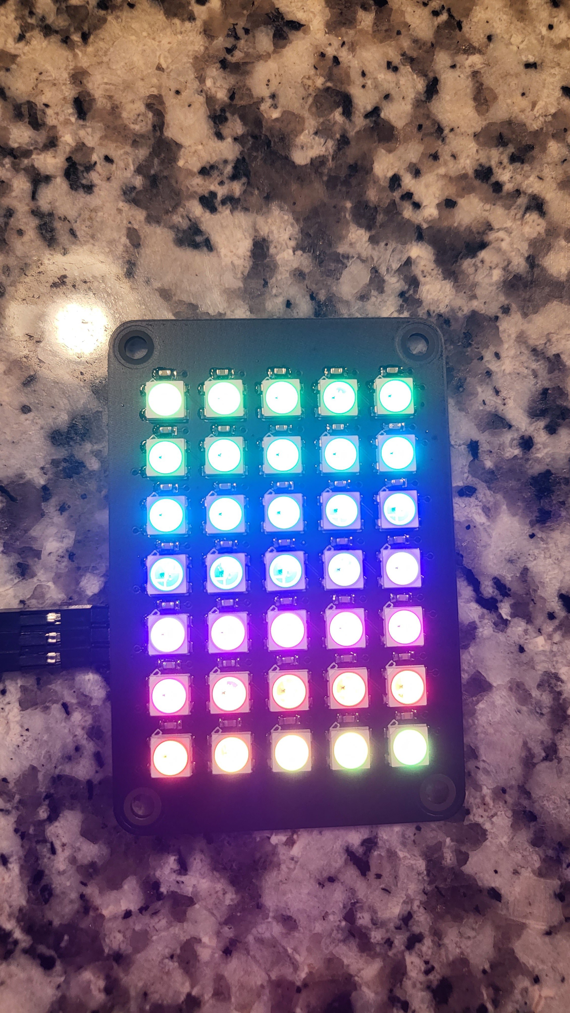
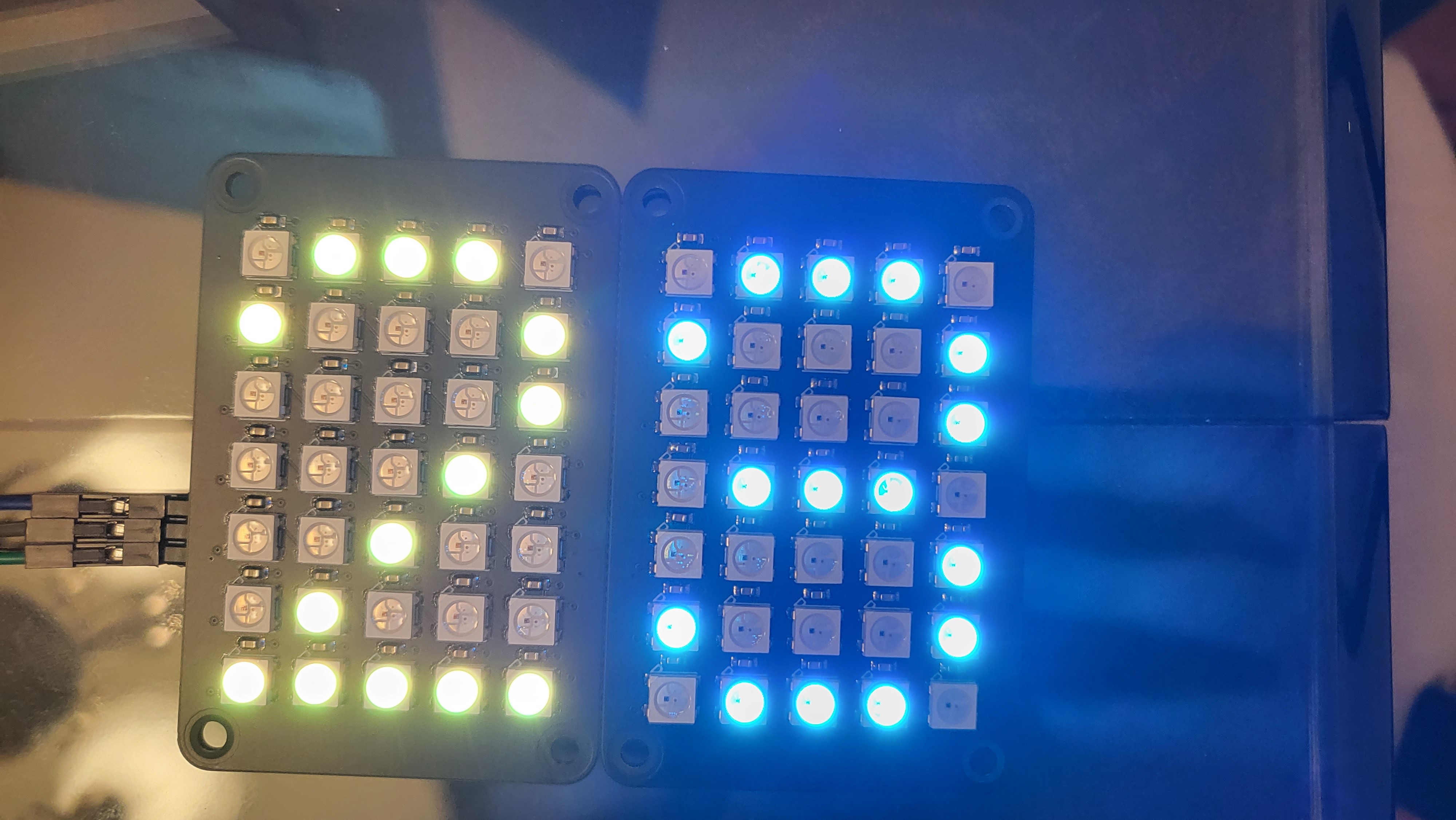
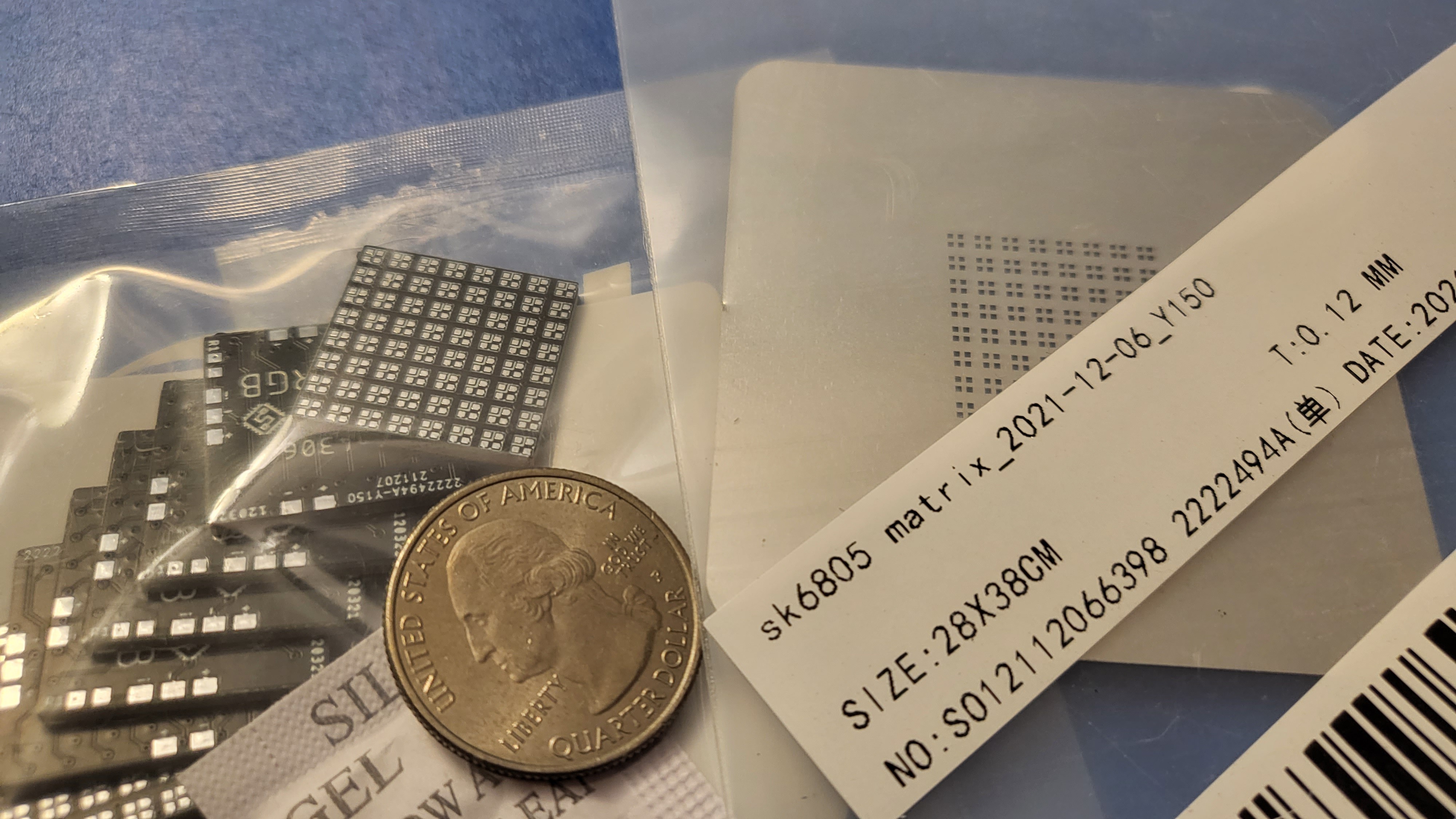
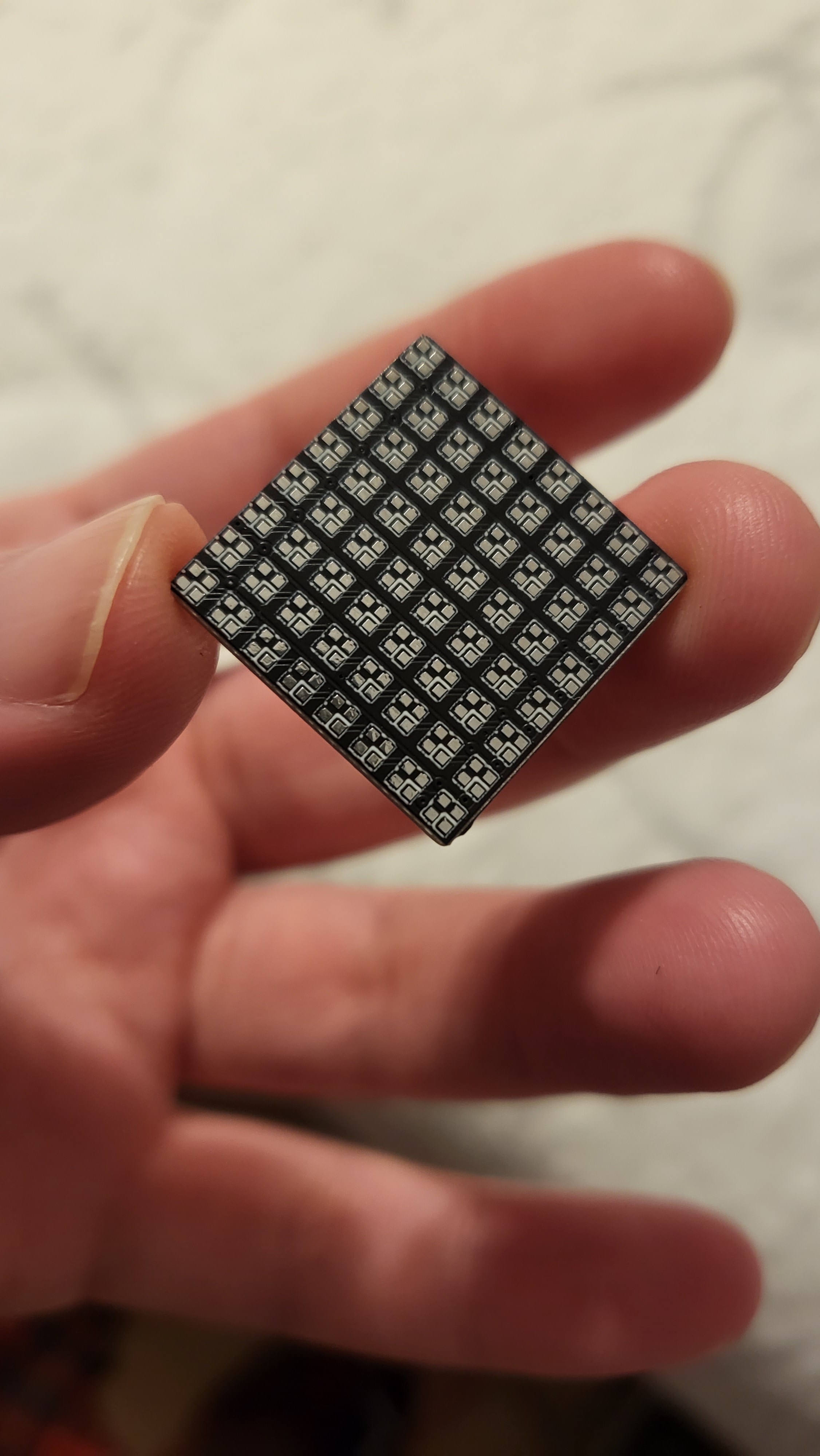
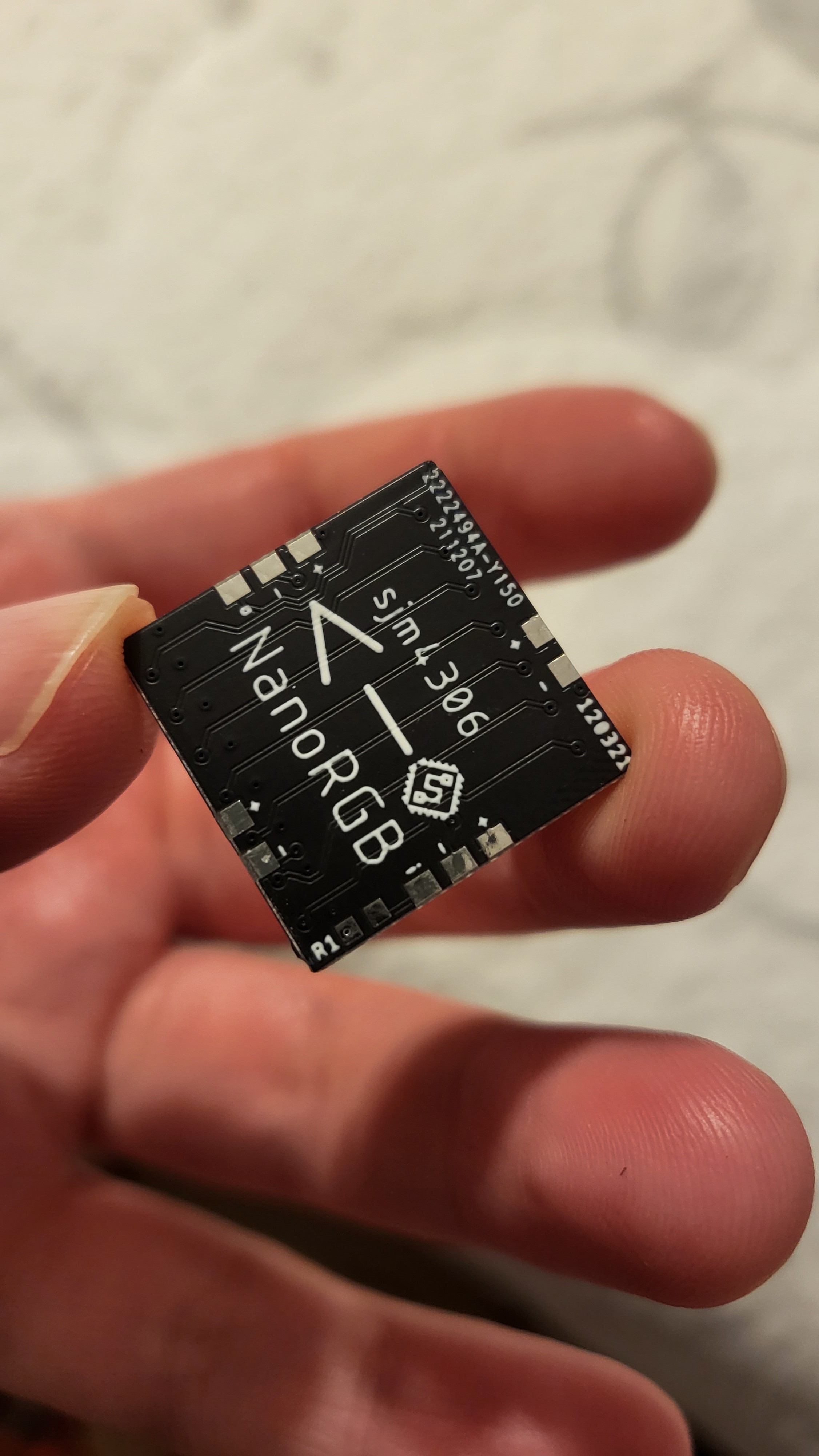
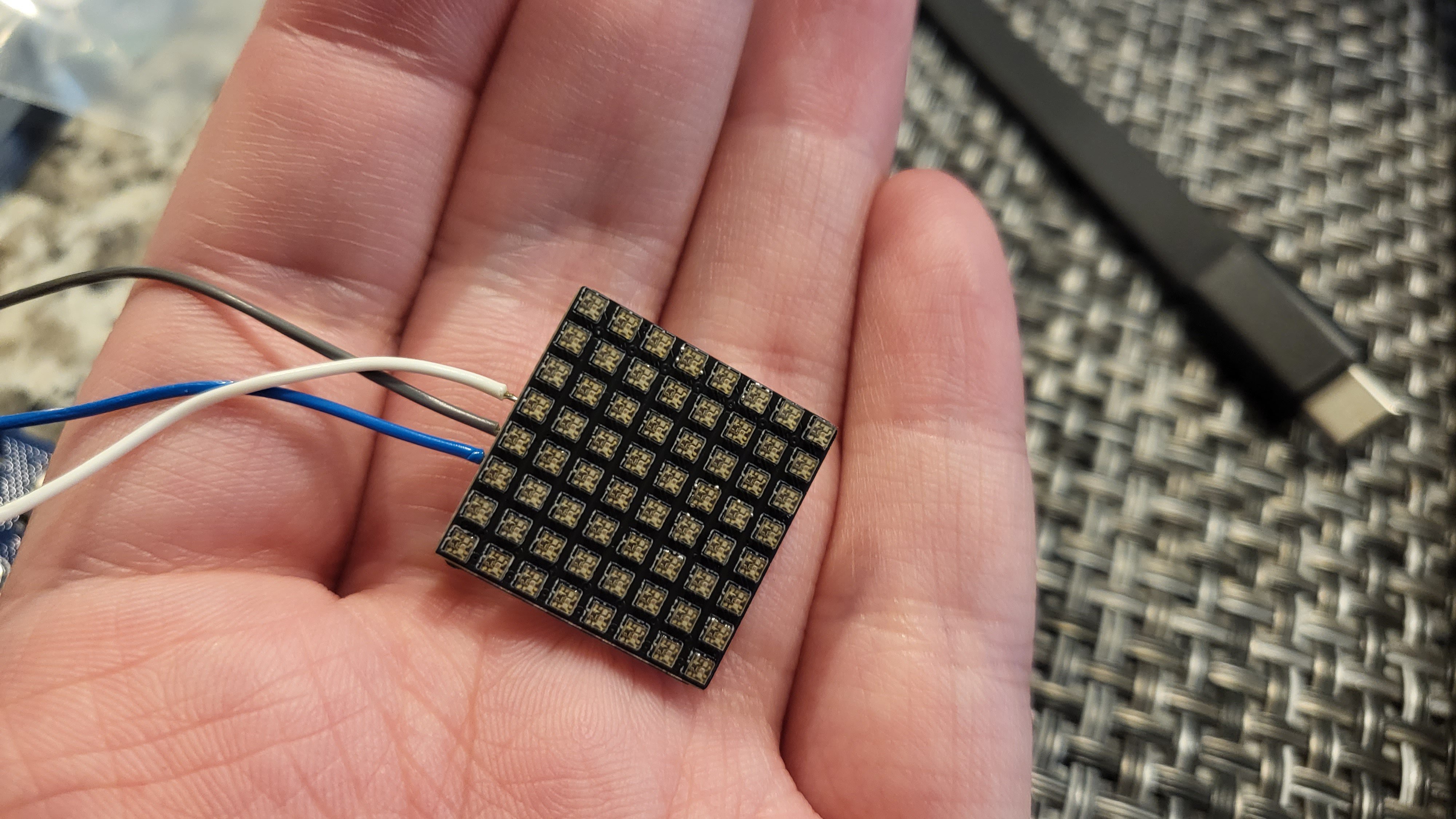
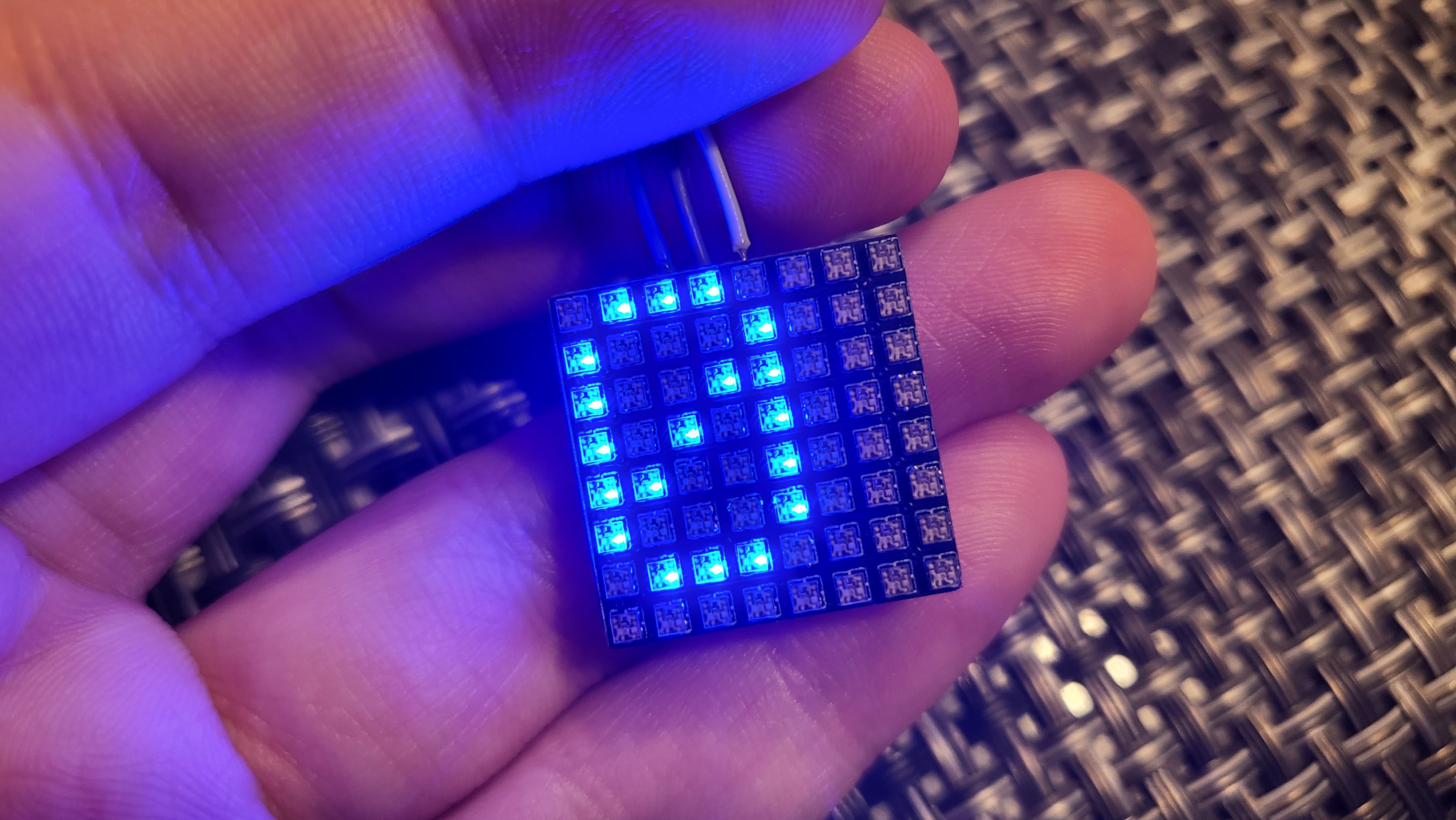
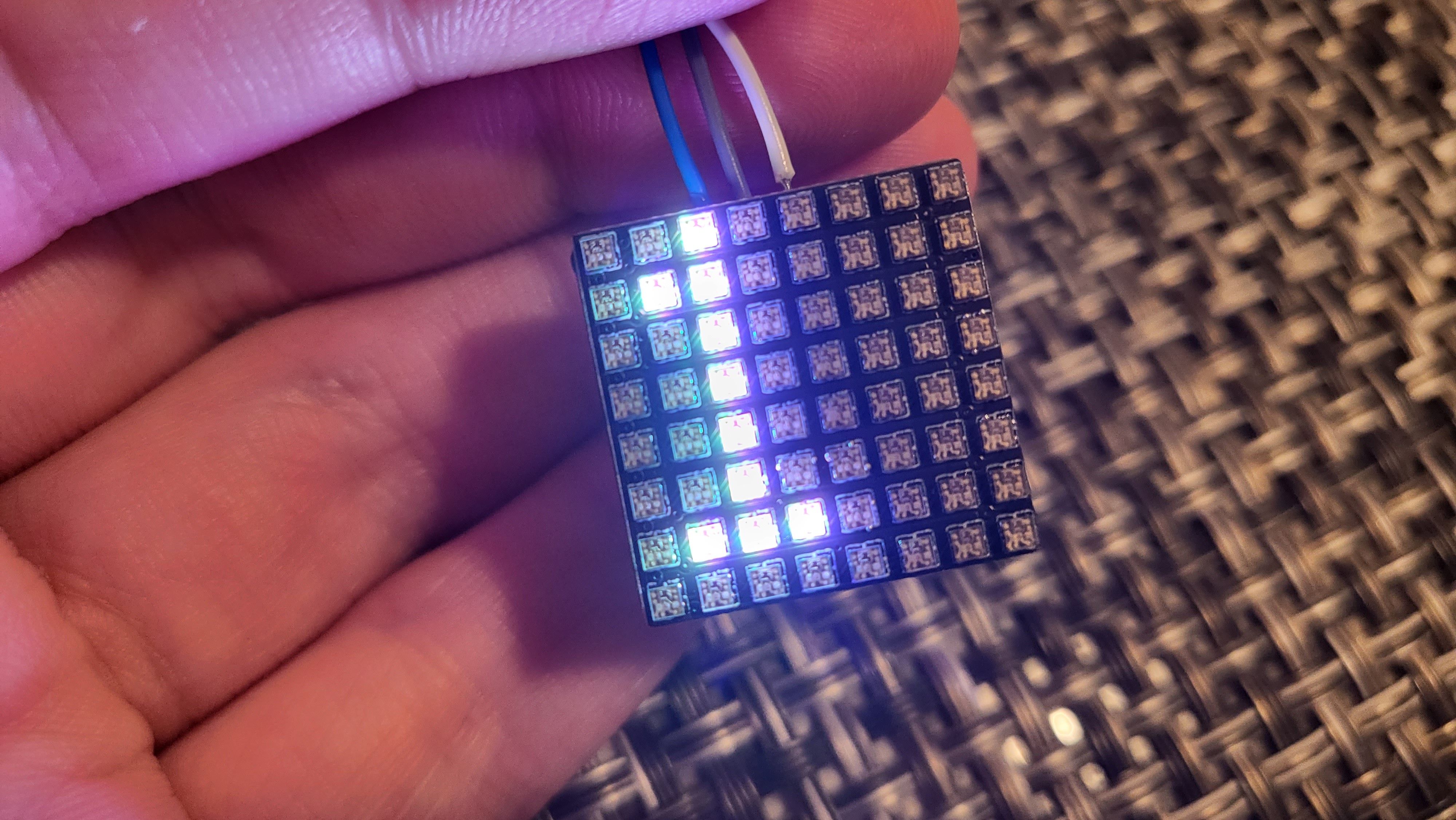
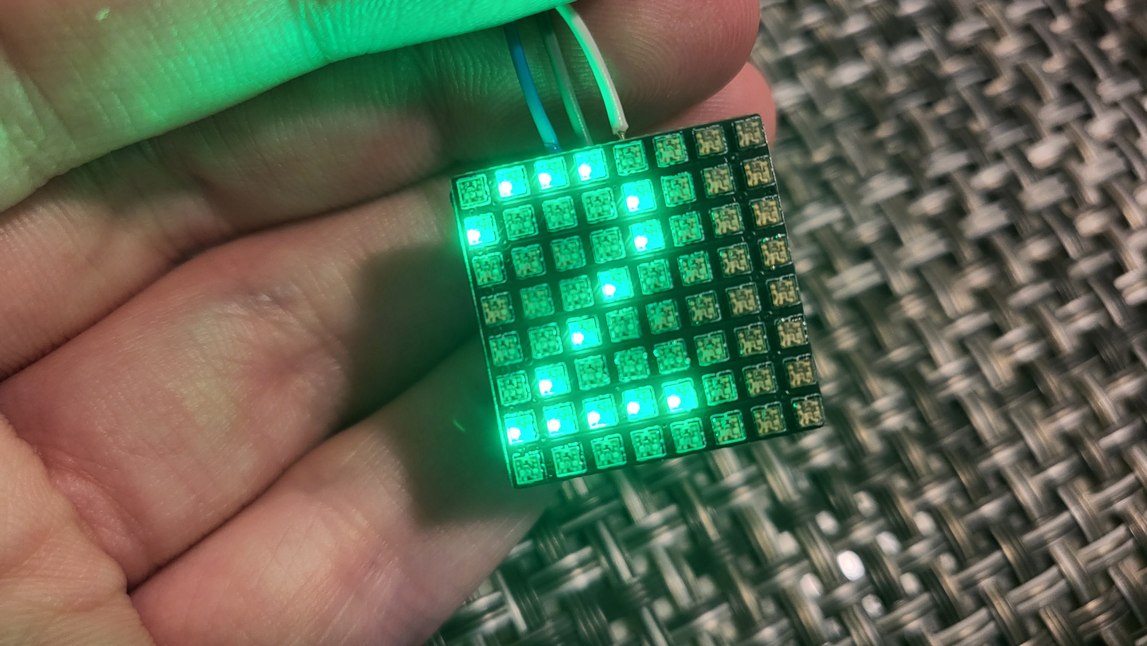
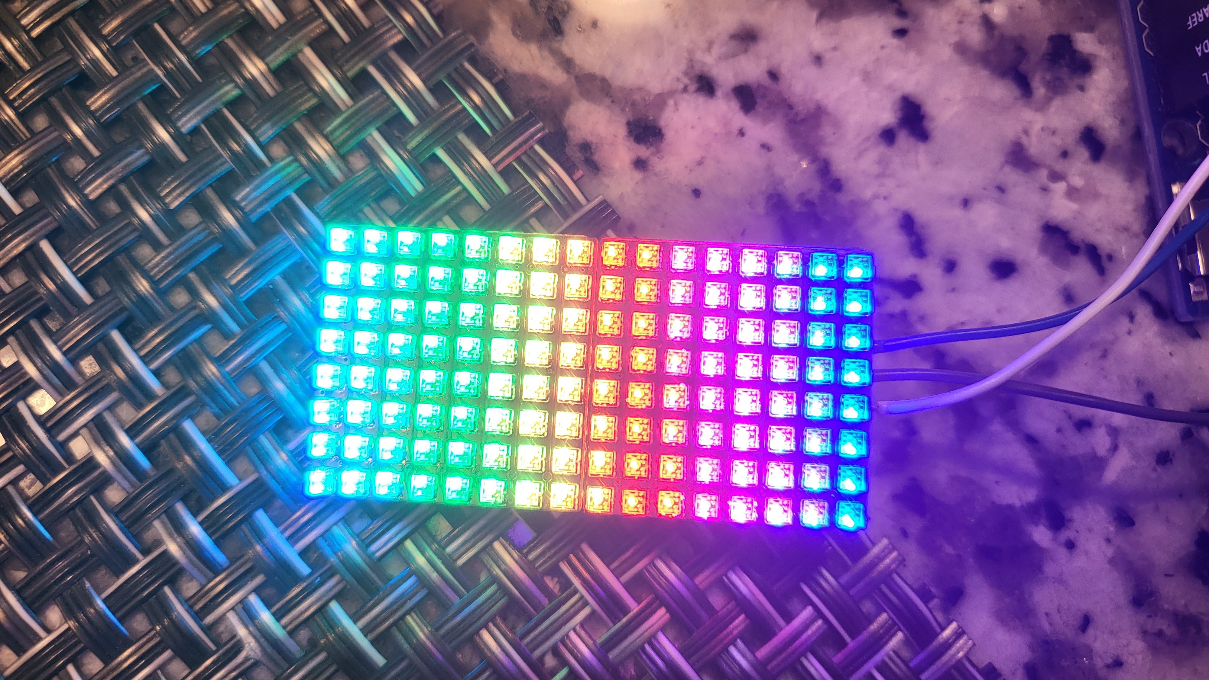
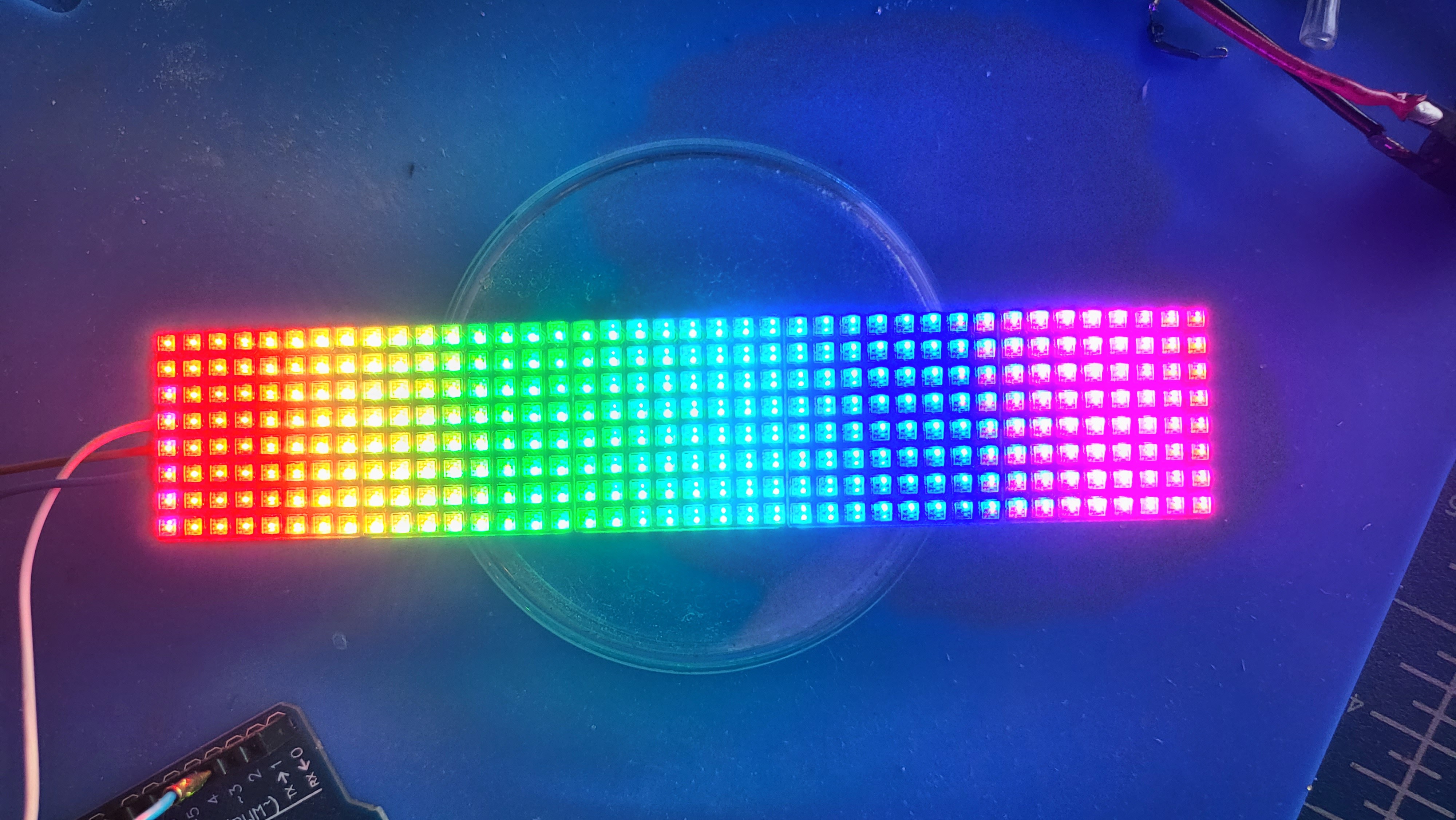
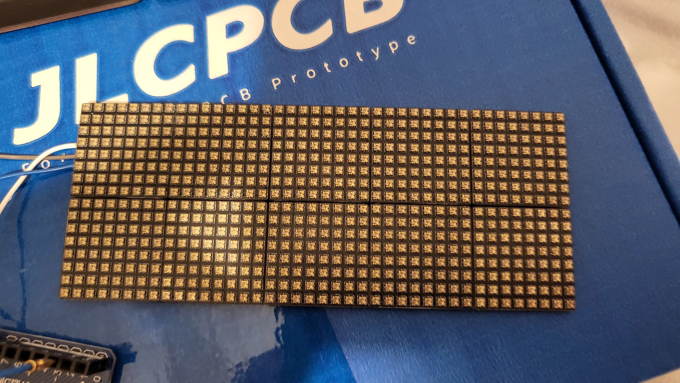
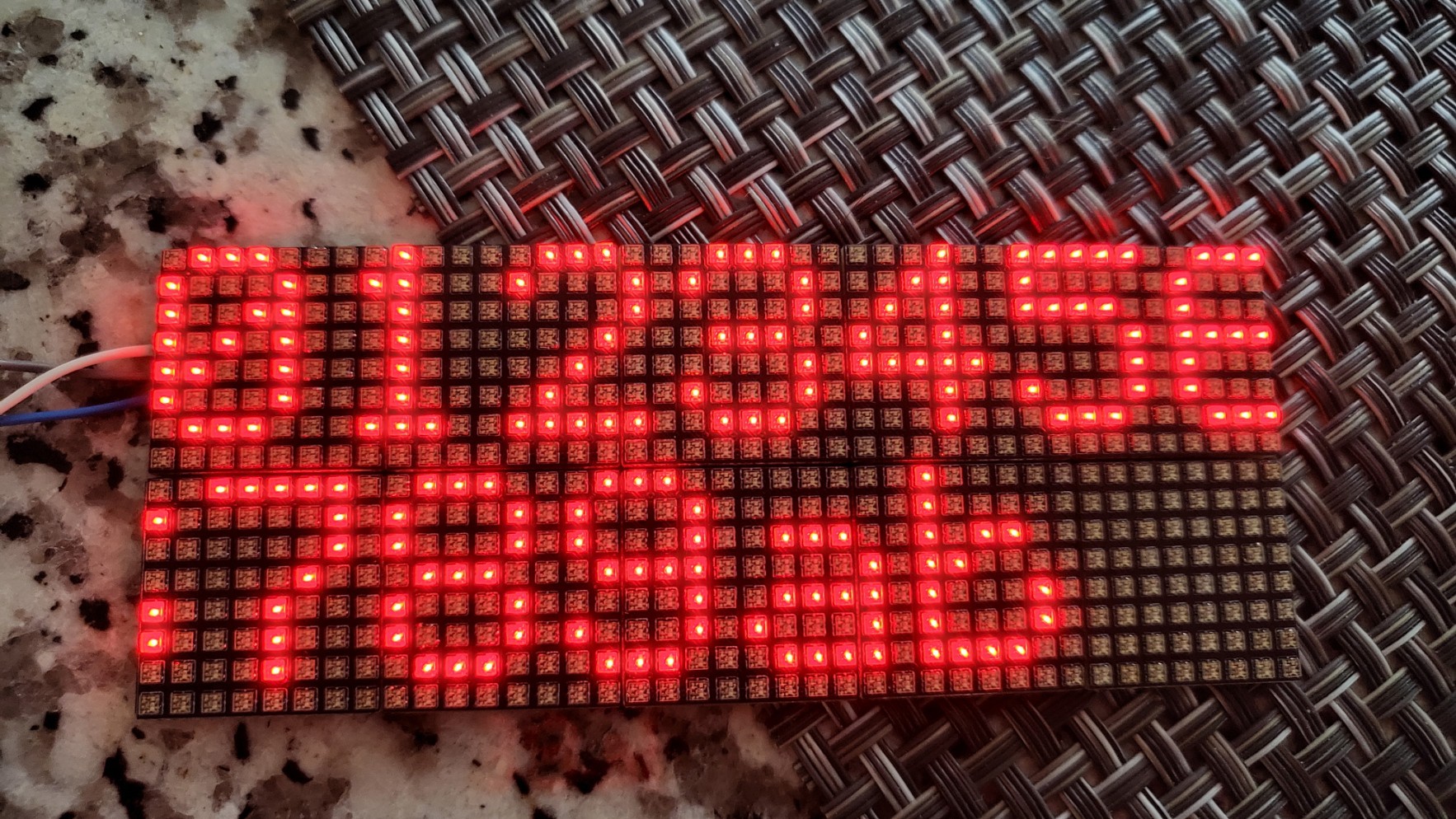
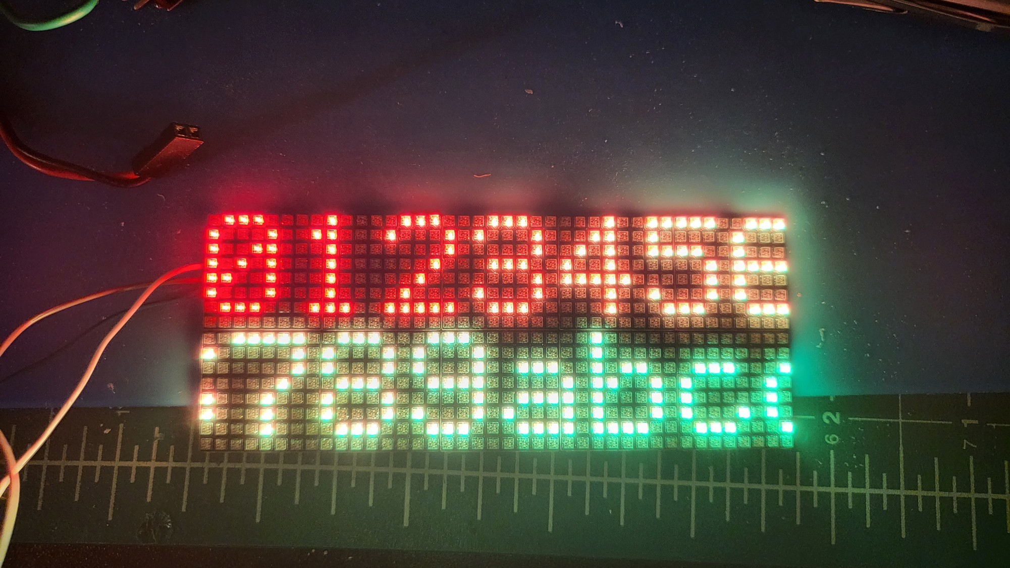
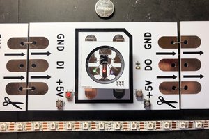
Tileable Tiny 8x8 SK6805 RGB Matrix
I've seen several tiny led matrices based around the diminutive sk6805-ec15 so I thought I'd throw my hat in the ring
 sjm4306
Become a Hackaday.io member
Already have an account? Log in.
Just one more thing
To make the experience fit your profile, pick a username and tell us what interests you.
Pick an awesome username
hackaday.io/
Your profile's URL: hackaday.io/username. Max 25 alphanumeric characters.
Pick a few interests
Projects that share your interests
People that share your interests


 blinkingthing
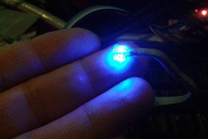
 Morning.Star
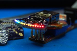
 zakqwy
 Mangus Tiranus
Hi , I love these , are , by chance, in production?