 Dave Collins
So for a while now I've wanted to build a small power supply for the ALU project. I really didn't want to spend a ton of time laying one out, and I didn't want to loose a ton of focus specifically working on the power supply because, I feel like I have a good clip on the ALU build. So stumbled across this project on CurcutDigest its simple; slightly sketchy, but it works.
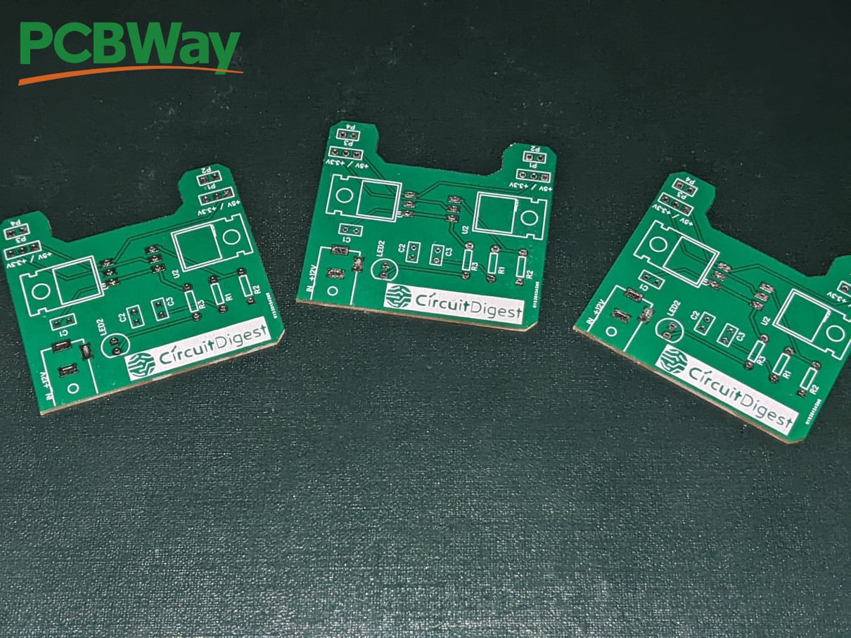
About a week or two ago, this project started picking up some steam, and it found some notice with the folks over at PCBWay! They had offered to supply the PCB's if I would review their services. I've already used their services on some of my other projects, and have already been very happy before so I saw no issue putting this together for them.
First, the process was simple, just uploaded the Gerber files, clicked a few buttons selected a color and before I knew it the boards were on the way. It took about a week, using standard shipping the total cost with shipping came to about 20 dollars, for 5 boards, had I paid for them. Honestly for rapid turn PCB prototyping, the price is reasonable and competitive for the quality that you get. I've used a few different companies to have this done, and the quality PCBWay, for the cost, is hard to beat.
Lets talk about the CurcutDigest DIY Breadboard power supply:
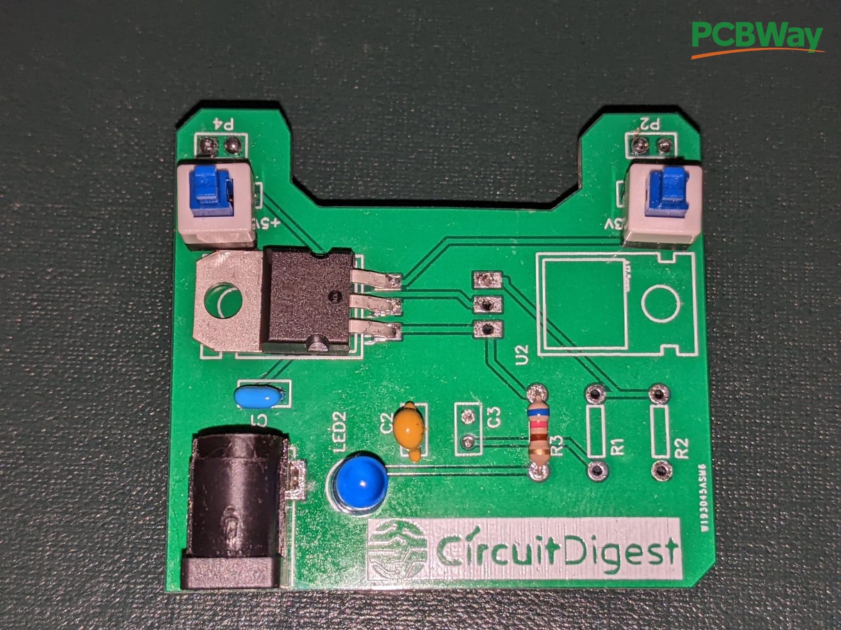
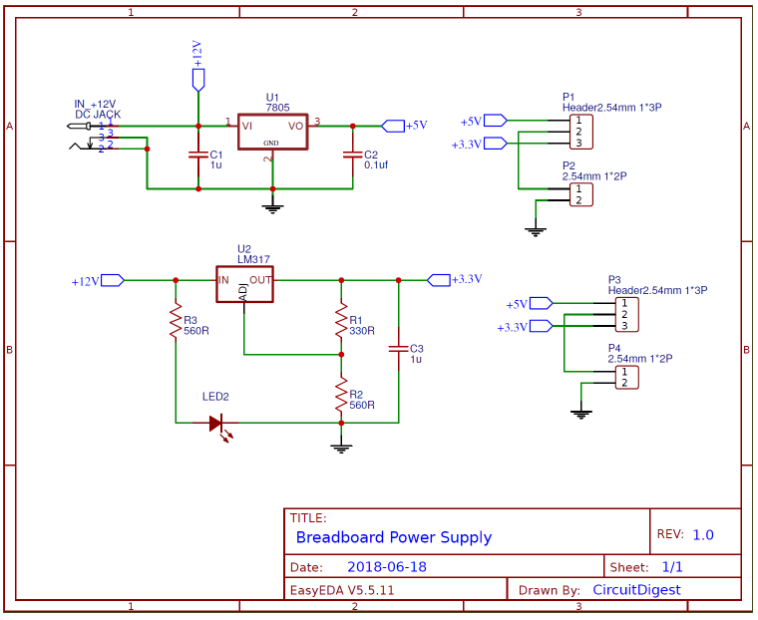
The power supply is very simple, it uses a standard 8705 linear voltage regulator. and also has space for a LM317 Variable voltage regulator which can be configured for a second voltage, the design specifies values for a 3.3v regulated supply.
In my case I only built up the 5 volt side, and power LED. I also replaced the jumper blocks with 1 side of a few latching SPDT switches. The key to this configuration was making sure the switch covers the expected current for the circuit, in my case I think I am fine but it's something to watch if you want to try this mod. The nice part is you can use the latching switch to turn the power on and off from the board quickly without unplugging the supply from the wall.
Issues and complications:
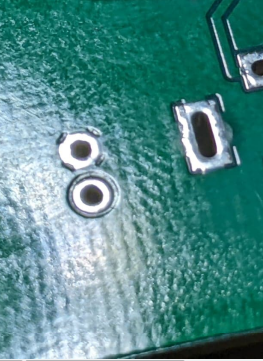
When I built this supply Initially I had to start over on a new board because I tired to use a tip that was too small for the large ground planes, which cover both sides of the board; along with trying to use lead free solder that was still set up in my station. the results were not pretty:
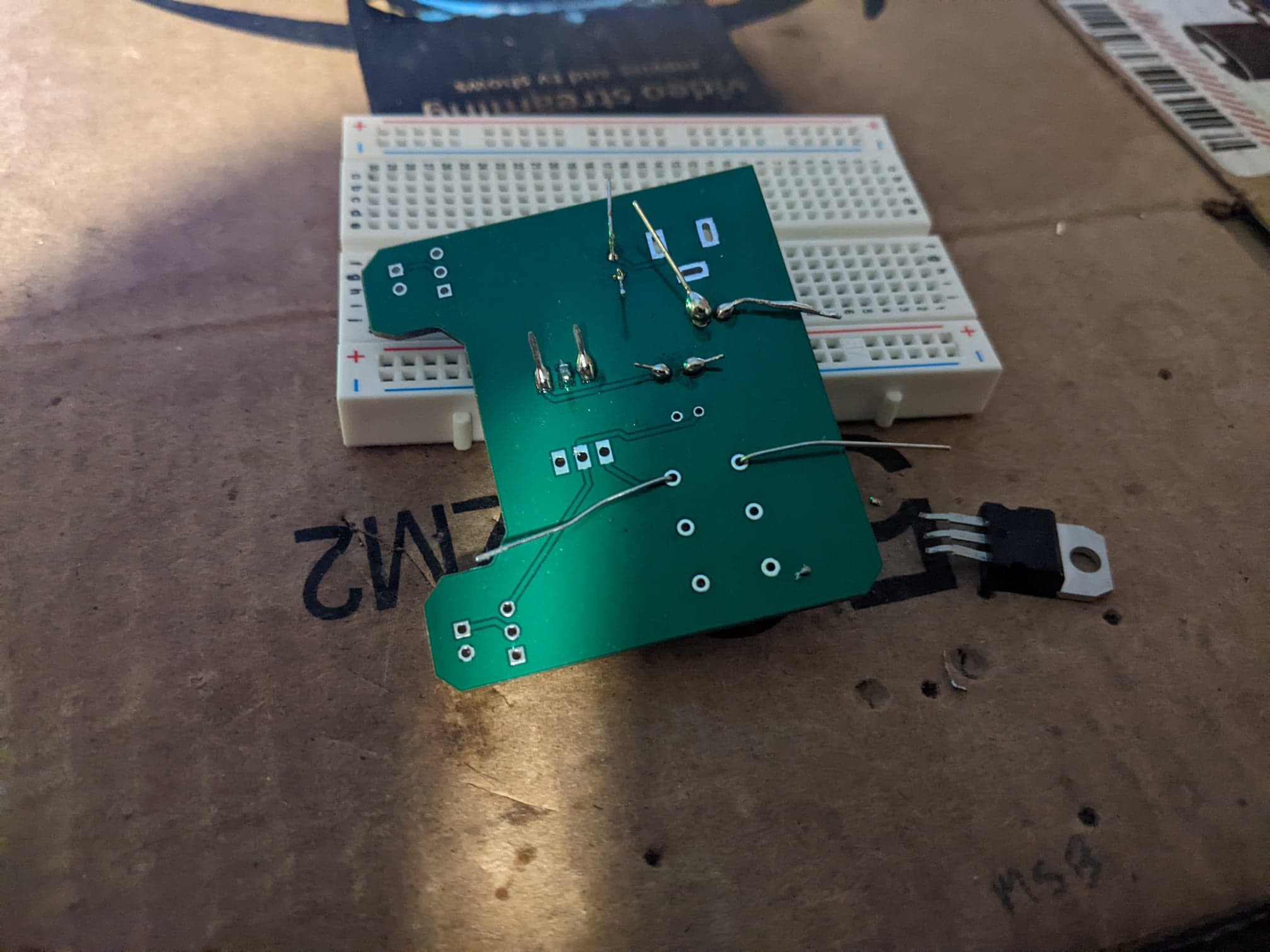
I ran into some real issues with the very small modern through hole capacitor footprint, this resulted in some very poor soldering and i ended up damaging a regulator. I switched to a larger flat tip, with some 60/40 solder and everything went much better. The boards were also HASL finish, and I've had some issues with fine soldering trying to use mismatched solders like that, its 100% an error in judgement on my part, and not the blame of the board making process.
Another issue I ran into is:
The ground pin for the power LED, pictured here is towards the inside of the board
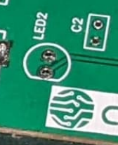
But as you can see, the silk screen is backwards. This is an issue with the PCB layout and not the manufacture, and another think to keep in mind if you build this board up, you have to install the LED in backwards, according to the silk screen.
Mechanically, the board could use another row of output bergstick pins, I think that would stabilize the connection to the board a bit better, with this set up I have to prop something under the supply so it doesn't fall off the end of the board. This might also be 100% my fault to begin with, as I have relatively cheep breadboards.
as you can see by the design, there is no heat sync on the regulator, and there's no protection diode, just simply the regulator and a few ceramic caps. Maybe at another time I can correct the schematics, and add some simple preventative measures for dead shorts and accidentally hooking up backwards, for now so I can move forward I'll be careful to unplug it, and make sure to check for major shorts before I add back power.
Performance:
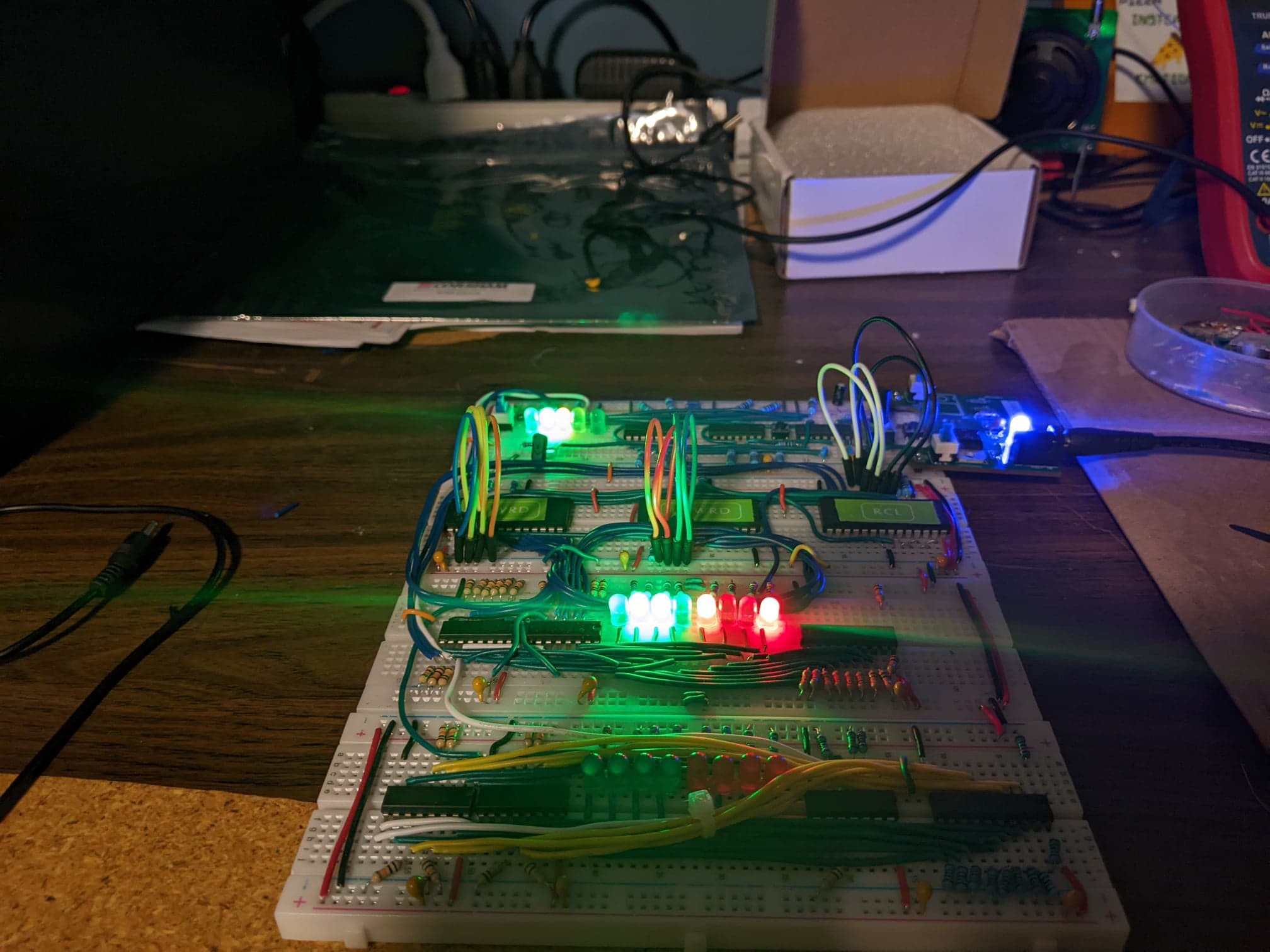
It seems to work well, both toggles work to turn the power on and off though I should point out you should put both switches in the same way if you want them to function in the same way. This seems silly, but I'll be honest it's relatively easy to do and I had to de-solder and re install one of the switches after I had the whole board cleaned with IPA. The 5.032 volts I am getting out of this supply is better than the 4.8 I was getting from the USB cord with one end lopped off. The supply's designer says it has an upper limit of 1 Amp. I don't get any significant heat off the regulator with regular usage, I don't think i will get even close to that but the build is still quite young. All in all I am quite happy with this little side project. It went together in just about a week for a handful of parts I mostly already had, all told I don't think I would have spent more than 30 dollars on it, had PCBWay not kindly made the boards for me. Additionally I am left with a few spares, so I can make another if I need one without too much trouble. All in all I am very happy with the results.

Discussions
Become a Hackaday.io Member
Create an account to leave a comment. Already have an account? Log In.