 xdylanm
Overview
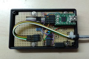
The Signpost is related to my Timing Gate project: it was an intermediate effort to experiment with powering a micro controller from a LiPo battery with a USB charger. The design is based around the Adafruit Trinket M0, and features
- a single button for mode selection
- two strips of NeoPixels as a display
- a PIR motion sensor
- LiPo battery power with a TP4056 charging module
The NeoPixel strips are independent for ease of assembly, but could be reduced to a single strip with the left and right sides managed in software.
Software is available on Github.
Power
The Trinket M0 has a nice on-board power path: battery and USB bus voltages are OR'd (through two Schottky diodes) into a AP2112 3.3V 600mA LDO. The AP2112 has a max 400mV dropout, but nominally that drops to less than 200mV below 400mA output current, so it works fine with a LiPo cell (3.7V - less than 200mV dropout - say 300mV Schottky diode = 3.2V). It can also easily regulate the battery while charging (4.2V).
Both input levels (3.7V for the battery, 5V for the USB bus) will power the NeoPixels. Technically, a level shifter is required for the data line from the M0 to the NeoPixels when the supply is 5V and the processor is running at 3.3V (spec says "high" is within 70% of Vdd), but everything will work fine on battery power. I've tried both (with the 74HCT125 as a level shifter and directly writing to the NeoPixels at 3.3V), and both work for prototyping. However, because both the battery and USB bus voltages are inputs to the LDO, prototyping requires a manual jumper to switch back and forth between sources.
The PIR module includes its own 3.3V LDO (mine came with an HT7133-1), which needs to be bypassed to power everything off of the 3.3V supply from the Trinket. This was done by removing the LDO with a hot air gun and soldering on a jumper (which should also qualify this build for HaD).

Display
The "display" for the signpost is two sets of 12 NeoPixels arranged in a staggered grid. To concurrentlysupport polling the mode button and PIR and displaying animated symbols, I wanted to avoid blocking calls to the display. To handle this, I added a frame clock based on a hardware timer interrupt. This is not well documented for the Trinket M0 and depends on some understanding of the SAMD21 datasheet. I used the following examples & notes
- https://gist.github.com/jdneo/43be30d85080b175cb5aed3500d3f989
- https://gist.github.com/nonsintetic/ad13e70f164801325f5f552f84306d6f
- https://emalliab.wordpress.com/2021/04/16/comparing-timers-on-samd21-and-samd51-microcontrollers/
- https://ww1.microchip.com/downloads/en/DeviceDoc/SAM-D21DA1-Family-Data-Sheet-DS40001882G.pdf
and I'm grateful to the authors for putting those together. Basically, the SAMD21 has a collection of "timer/counter" (TC) modules that can be associated with various clocks (including the XO, etc.). The TC modules have some prescaling (max 1024), and support 8, 16 or 32 bit counters. Interrupts call a specific handler that is predefined. The 32 bit counters are made by joining a pair of TC modules, but I was not able to get that to work -- the examples above are all 16 bit counters, but in the end that was sufficient for my purposes (max time is 2^16*1024/48000000 = 1.3981 seconds). My implementation is in https://github.com/xdylanm/signpost/blob/master/sketches/signpost/samd21timerirq.cpp. I tried to generalize it a bit to target different TCs, but this could be improved.
Main Loop
With the frame clock as described in the previous section, the main loop
- checks the PIR state for an edge (and loads an appropriate animation if triggered)
- checks the (software debounced) mode button (and loads an appropriate animation if triggered)checks the
- mode animations can be interrupted so that the mode button can be quickly pressed repeatedly
- checks for a frame event and ticks the active animation if present
The frame clock is also used for the countdown timers, which cycle by
- display a start symbol (both left & right arrows simultaneously)...
 Christoph
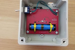
 Linus Dillon
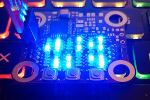
 programagor