Close
0%
0%

ADNS 3050 Optical Sensor & Mouse

A board to utilize the ADNS 3050 optical sensor and a fully 3D printable mouse

tomtom
Similar projects worth following
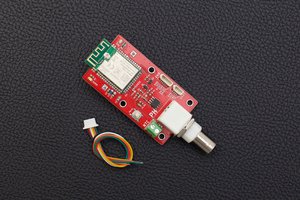
The board uses an ADNS 3050 optical sensor found in many entry level gaming mice. It can be used for robotics, custom gaming mice or anything that needs motion tracking.

I currently have a indiegogo campaign going for the sensor board listed below which also includes a video of the mouse in action.
https://www.indiegogo.com/projects/adns-3050-optical-gaming-sensor#/


The boards are now available for purchase on tindie here : https://www.tindie.com/products/tom10122/adns-3050-sensor-board/

Thank you to everyone for your support!

The sensor measures the change in the X and Y axis by taking multiple pictures and using its on-board DSP to determine the movement/change between them. It then stores the data in its memory which is accessed over SPI. The sensor can operate at up to 2000CPI and register acceleration up to 20G's


I have written a library to use with it that makes getting the X and Y movement pretty straight forward. I included some communication examples and the code and 3D models to make your own computer mouse.
  • 2 × M2 x 20mm Machine screw
  • 2 × M2 Nut
  • 1 × M2.5 x 20mm Machine Screw
  • 2 × MicroSwitches (mechanical endstops) Used for the left and right mouse button, common on 3d printers
  • 1 × ADNS 3050 Sensor board

View all 11 components

  • Instructable tutorial

    tom01/02/2017 at 22:37 0 comments

    Hi everyone, I wrote up a tutorial on instructables on interfacing the sensor with the arduino.

    Check it out here: http://www.instructables.com/id/Interfacing-With-a-Mouse-Sensor-ADNS-3050/

  • Available on tindie!

    tom12/28/2016 at 20:51 0 comments

    I just listed the boards for sale on tindie! They can be found at: https://www.tindie.com/products/tom10122/adns-3050-sensor-board/

    I really appreciate all the support I have received and can't wait to get started on my next project, thank you everyone!

  • The Sensor WILL be made!

    tom12/05/2016 at 23:26 0 comments

    I spoke with my sensor supplier today and they are willing to work with me on the minimum order quantities ! This means, I can fund it entirely with personal funds, and about a month of waiting is by-passed ( the remaining days in the campaign and the time required for the funds to clear). Parts are ordered and the new ETA is Early-to-Mid January. I will also be doing another campaign on indiegogo with flex funding for pre-orders and to try to offset my costs as much as possible. I will post an update to the kickstarter as soon as the indiegogo campaign has been posted and an update here with the link also. (Kickstarter will be canceled) Thanks to everyone for their support! I can't wait to get building and ship these out.

View all 3 project logs

  • 1
    Step 1

    3D print both parts, top requires support, the baseplate should be fine depending on the printer.

  • 2
    Step 2

    Solder to the sensor board, place the lens in the center rectangle then place the sensor on top of the lens making sure that the sensor has the yellow kapton tape removed and the sensor sits in the small circle on the lens

  • 3
    Step 3

    Solder to the middle and 1 outer pin of each microswitch (each switch should have one pin to ground and another to the arduino) Solder at a right angle to the switch so it fits easily.

View all 6 instructions

Enjoy this project?

Share

Discussions

tom wrote 01/14/2019 at 00:15 point

HI everyone, I ordered enough parts for another production run so the sensor is back in stock. Thank you to everyone that bought it over the last two years and to anyone who buys it in the future!!

  Are you sure? yes | no

Similar Projects

Does this project spark your interest?

Become a member to follow this project and never miss any updates