 mircemk
This time I will show you how to make two simple but very sensitive EMF (Electromagnetic Field ) Detectors. Electromagnetic fields are a combination of invisible electric and magnetic fields of force. They are generated by many devices like power lines, kitchen appliances, mobile phones, computers, but they are also generated by natural phenomena like the Earth’s magnetic field.
Get PCB Prototype Free Trial Order: https://www.pcbgogo.com/promo/from_MirkoPavleskiMK
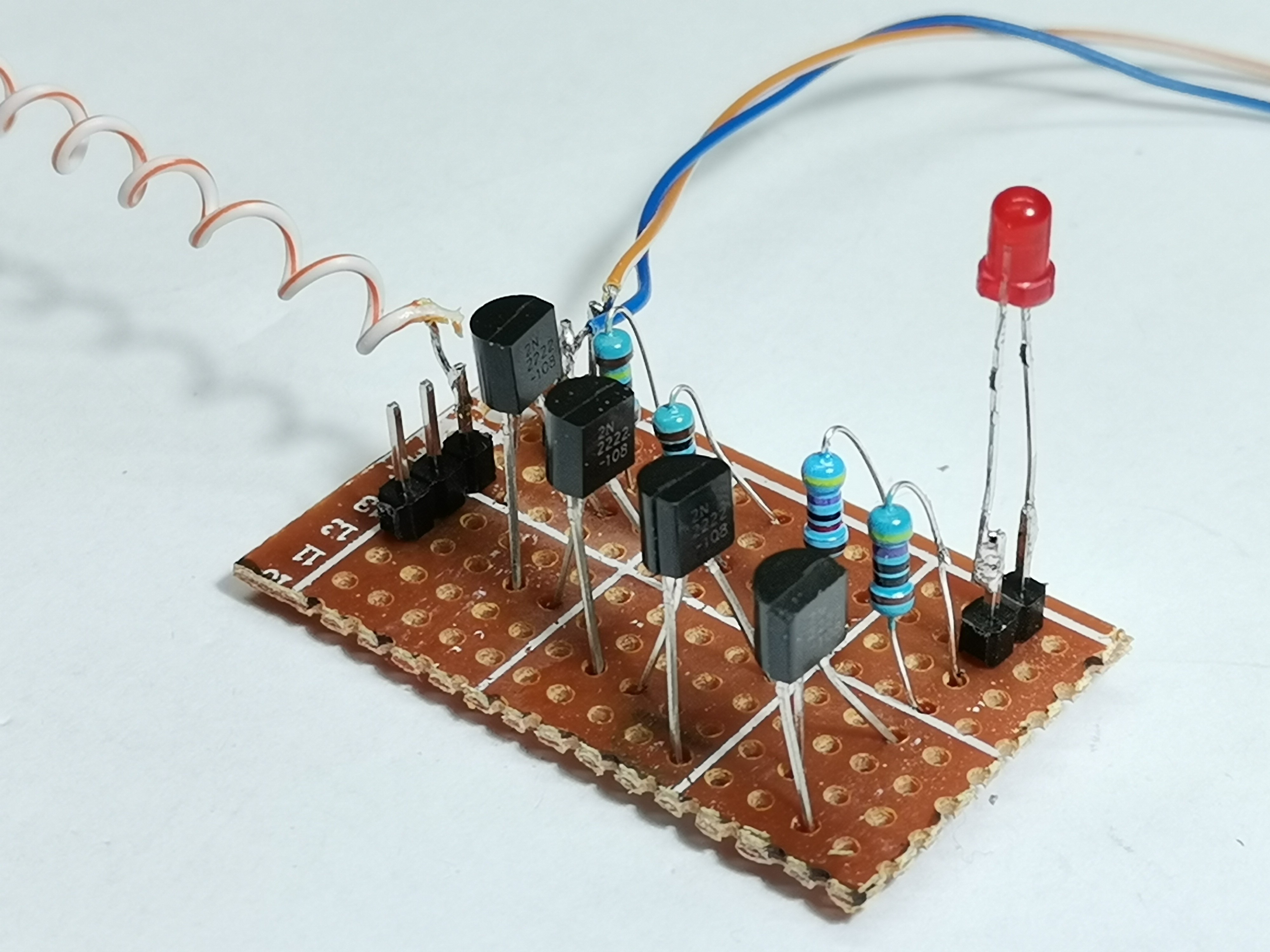
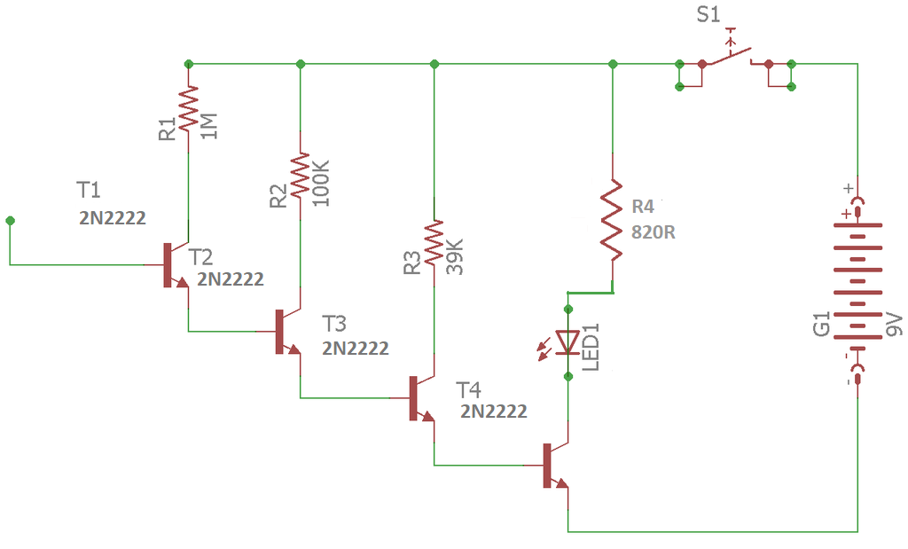
Many such projects can be found on the Internet, but most often the only proof of their sensitivity and functionality is the text in the description of the project itself. So I decided to make two devices, one with discrete elements (transistors) and the other with an Integrated Circuit, and test their features that are shown in the video. First, let's analyze this device made with 4 transistors connected in cascade form. It consists of four NPN transistors, four resistors, and one Led diode. The overall gain is the product of the individual gain of each transistor. The last transistor is connected to a LED diode that signals the presence of static electricity or EMF. In fact, this device is not an EMF detector, but a static electricity detector is known as an Electroscope, specifically this is an Electronic Electroscope. A thin aluminum plate is used as the antenna, and the device is powered by a 9V battery.
Let's first look at how it responds to static electricity. We get a static charge by rubbing a plastic object from the substrate. As we can see, the electroscope responds well to this type of charge. In contrast, the EMF detector does not respond to static electricity. Next, let's test this device near a weakly changing electromagnetic field. In this case, we have to move the detector very close to the source of the EMF to light the Led.
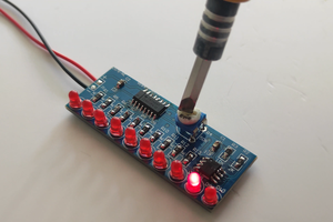
Let's analyze other which is extremely simple to make. Contains only one 4017 decade counter IC, resistor, and LED signaling diode.
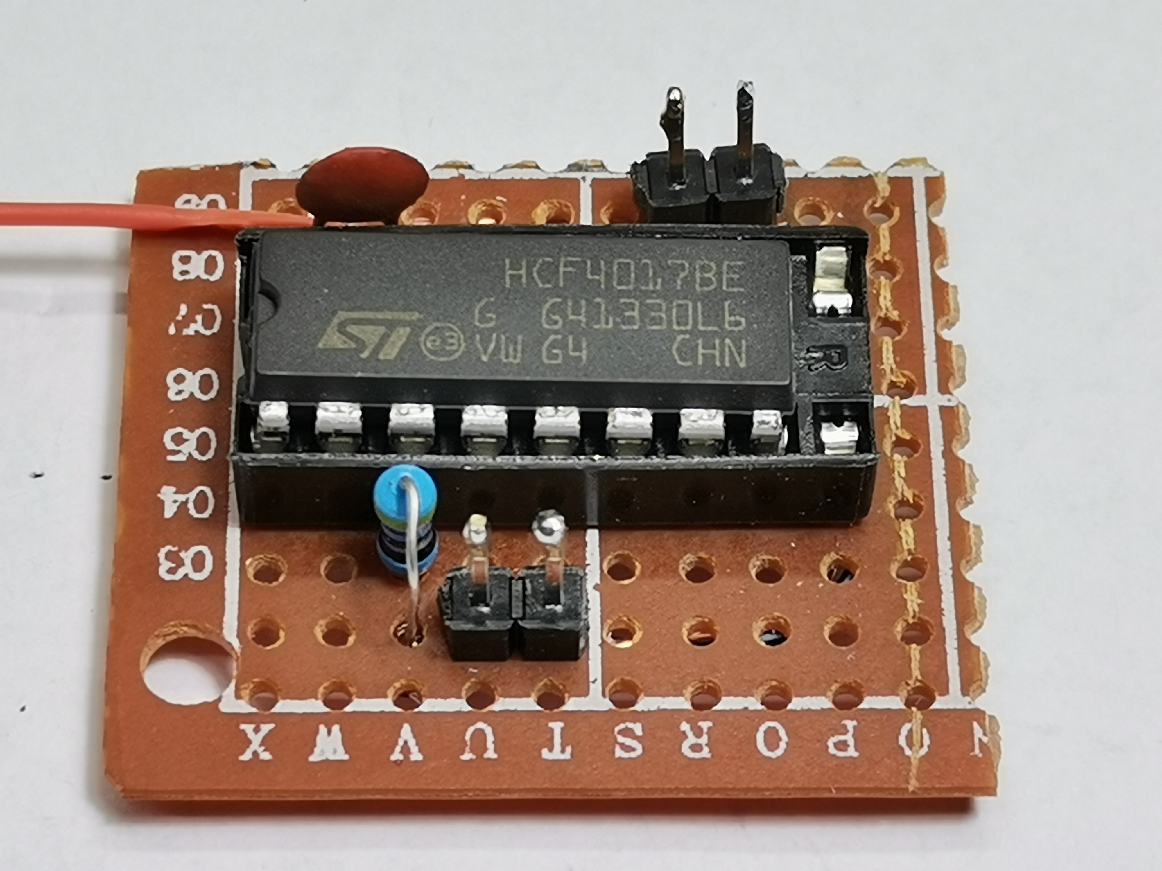
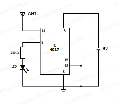
The output of the counter IC shifts from output 0 to output 9 for each positive edge of the pulse received at clock input pin 14. The clock input of the 4017 IC has very high sensitivity, a small pulsating signal can provide an input clock for the counter. When the probe comes near to a current-carrying conductor, an emf is induced in the probe due to the magnetic field around the conductor. This EMF gives the signal to the clock input. As the LED has attached to one of the 10 output of the IC, the LED flashes once for 10 clock pulse inputs. Hence, in a normal 50HZ supply, the LED flashes at a rate of 5 times per second. The sensitivity of the circuit will vary with the length and the shape of the antenna. In this case, it is also a thin aluminum plate. let's bring the detector closer to a weak electromagnetic field. let's bring the detector closer to a weak electromagnetic field. If the LED is continuously on or off, then there is no EMF presence. The sensitivity of this detector is incredibly high, considering that this is an extremely simple electronic device. It detects the field of a heater in my room at a distance of 30 cm and more.
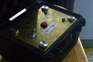
Finally, I would like to mention that these devices can also be used as lightning detectors, and a larger antenna should be used for greater sensitivity. We can also find them under the name Ghost Detectors. I placed them in a suitable compact box made of PVC material with a thickness of 3 mm, coated with self-adhesive colored wallpaper. Also in one of my previous videos, you can see 3 more similar devices used as Lightning Detectors:


Great video and very easy to make circuits thanks. What would be really great would be a quantitive electroscope. I realise it may be difficult to calibrate such an instrument very well, but if we could derive an approximate calibration just from circuit analysis that would be useful. The cascade circuit gain depends on the gain of each transistor and the tolerance of these us pretty wide leading to a very unpredictable total gain. Could a more predictable gain be achieved with a carefully selected op amp?