 courcirc8
Disclaimer: I did this project for myself. If the hack is relatively easy I would not encourage anybody to do it without knowledge since there is risk to damage your guitar, sound-card or smart phone if not done properly.
The first step is to remove the unnecessary parts of the guitar.
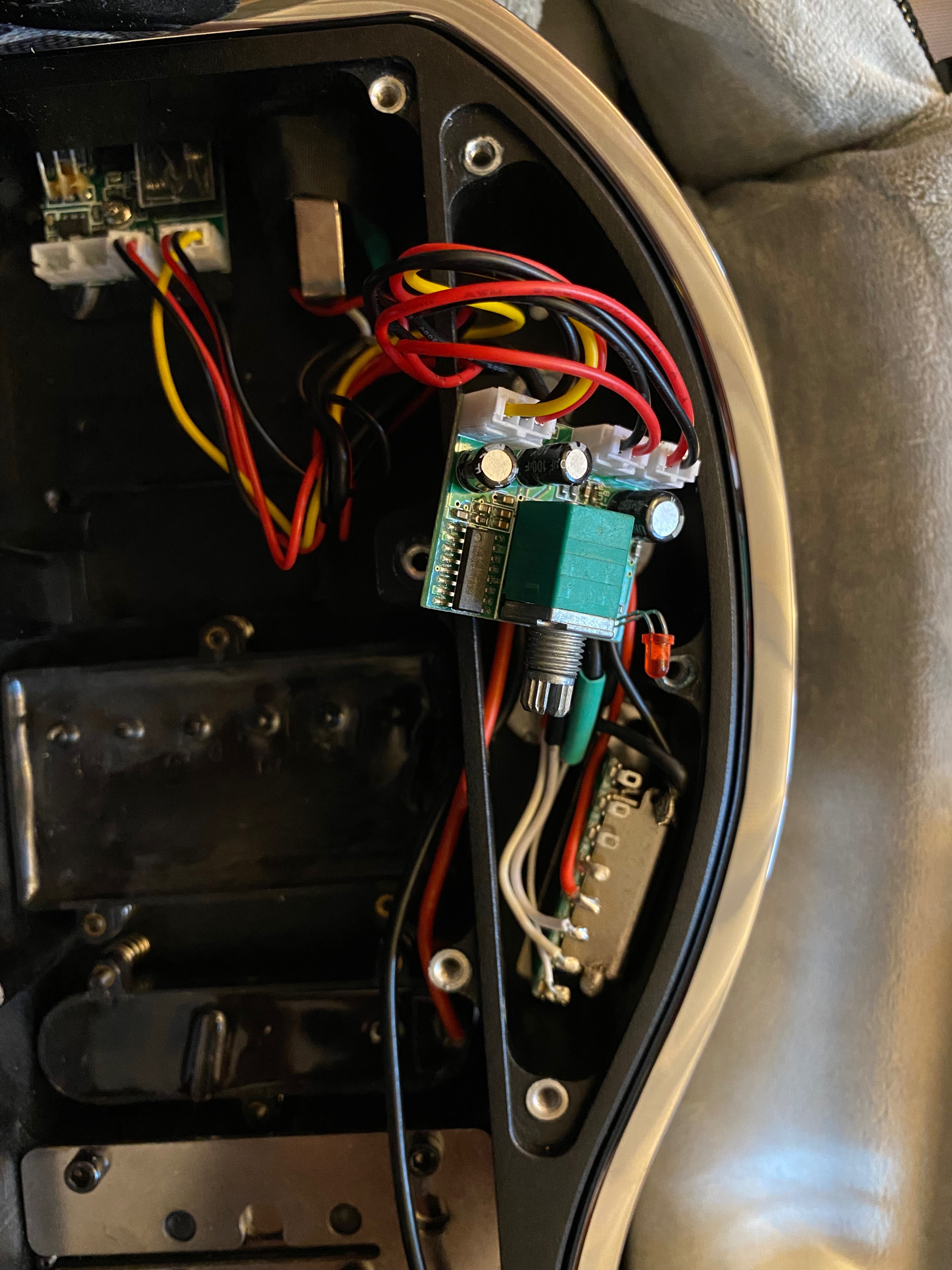
- remove LiPo battery
- remove input connectors and supply board
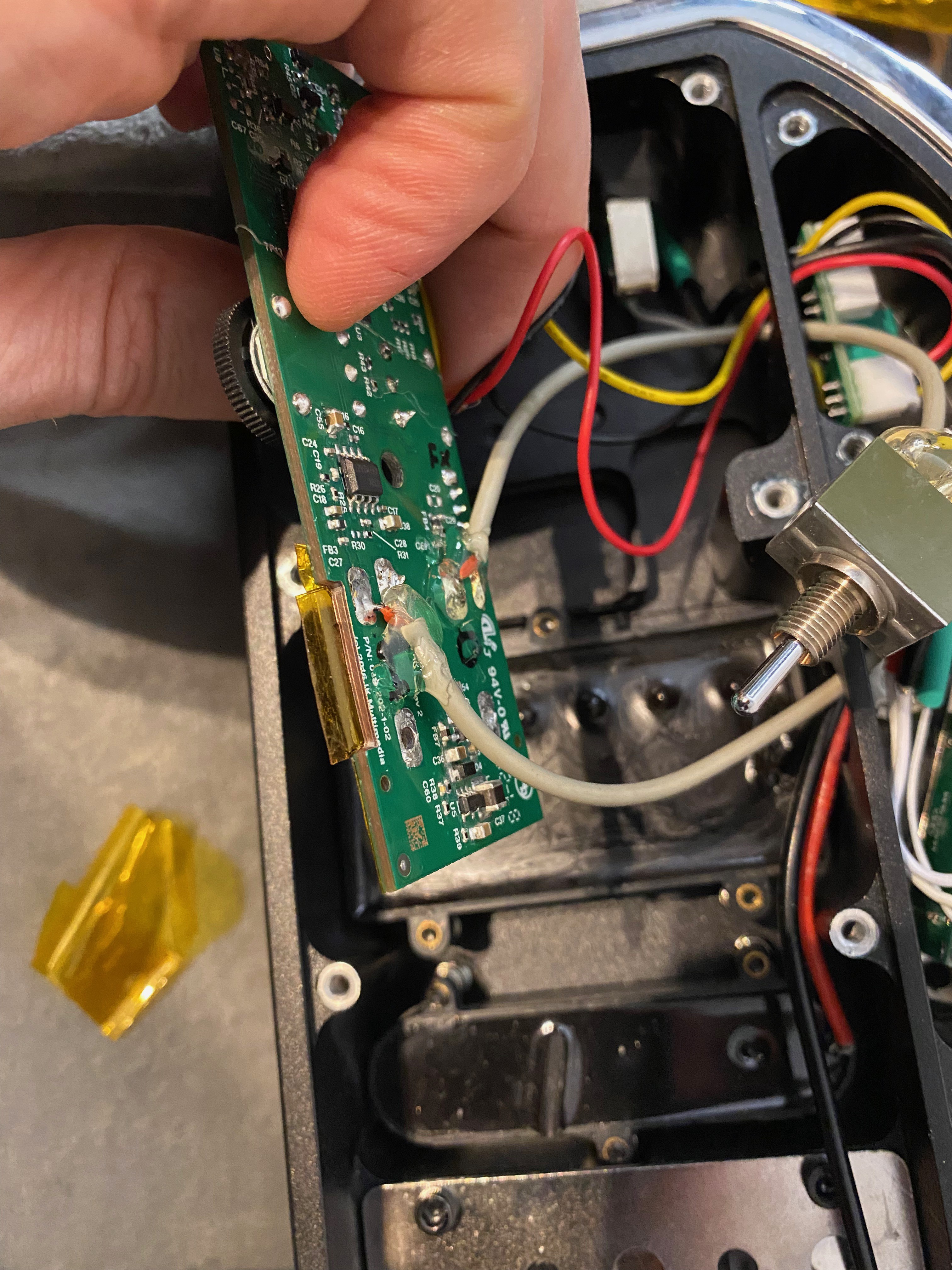
- remove volume pot/amplifier PCB (the one close to led, will be re-used)
- remove tone control pot (middle, later replaced by 2-way switch clean-disto)
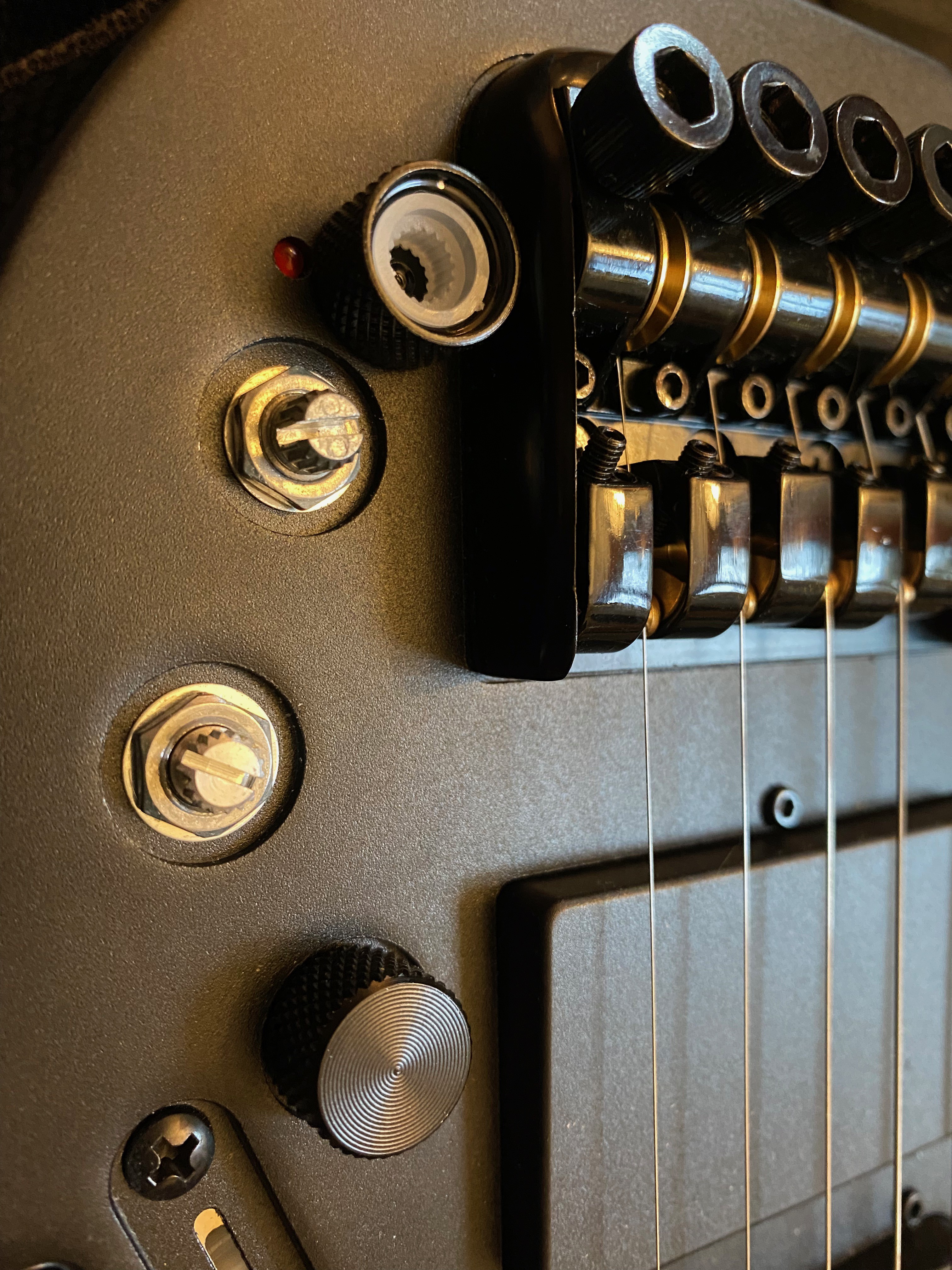
After battery and pot removal:
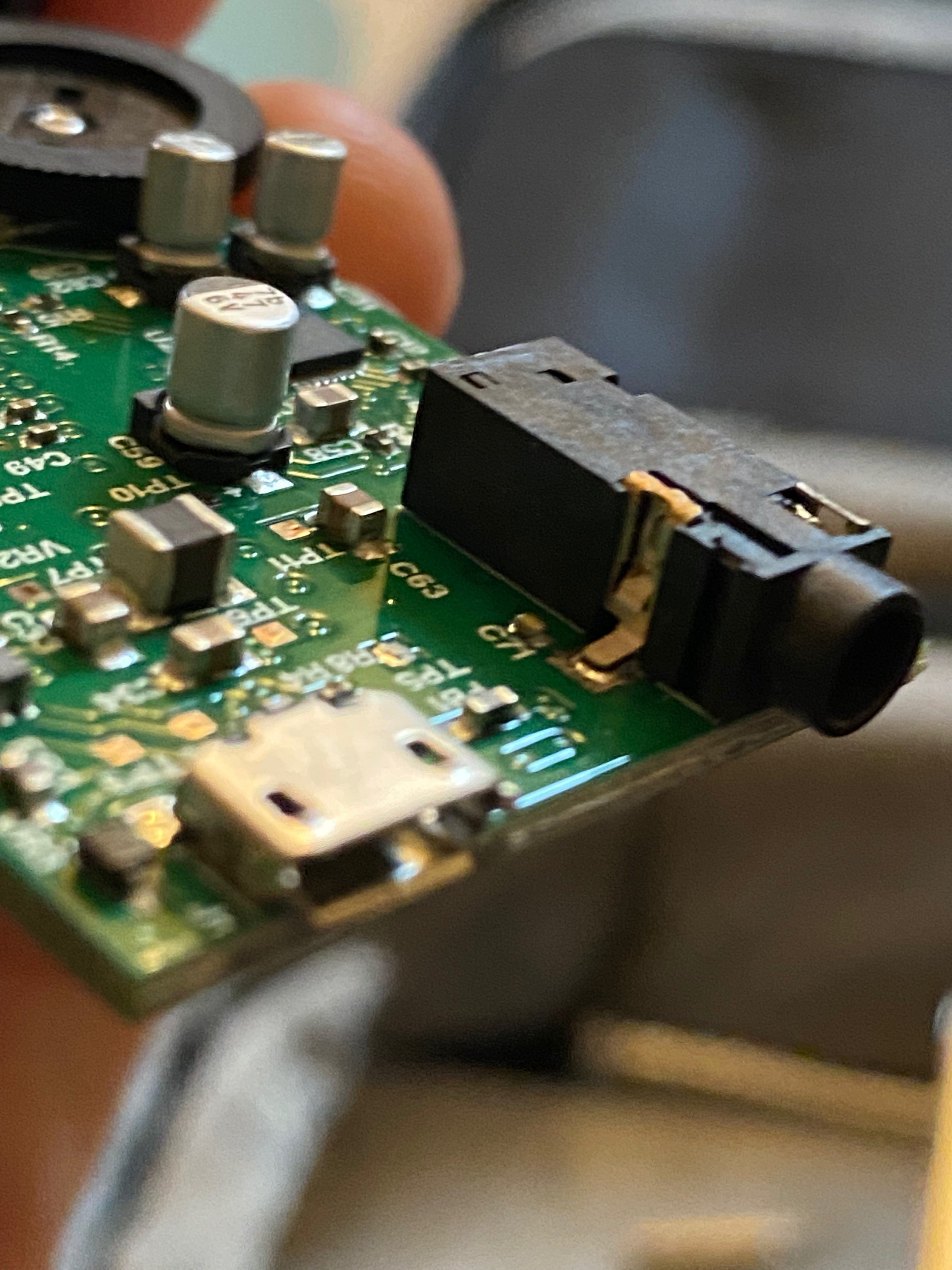
For this hack I used an USB audio interface compatible with PC, MAC and smartphone: the Irig HD2: IK Multimedia - iRig HD 2
You can connect it to amp emulation apps such as garage band or Bias Amp (positive grid) to have high quality amp sounds.
My sound-card was used and needed some fix first around the audio connector (re-solder or even better replace):
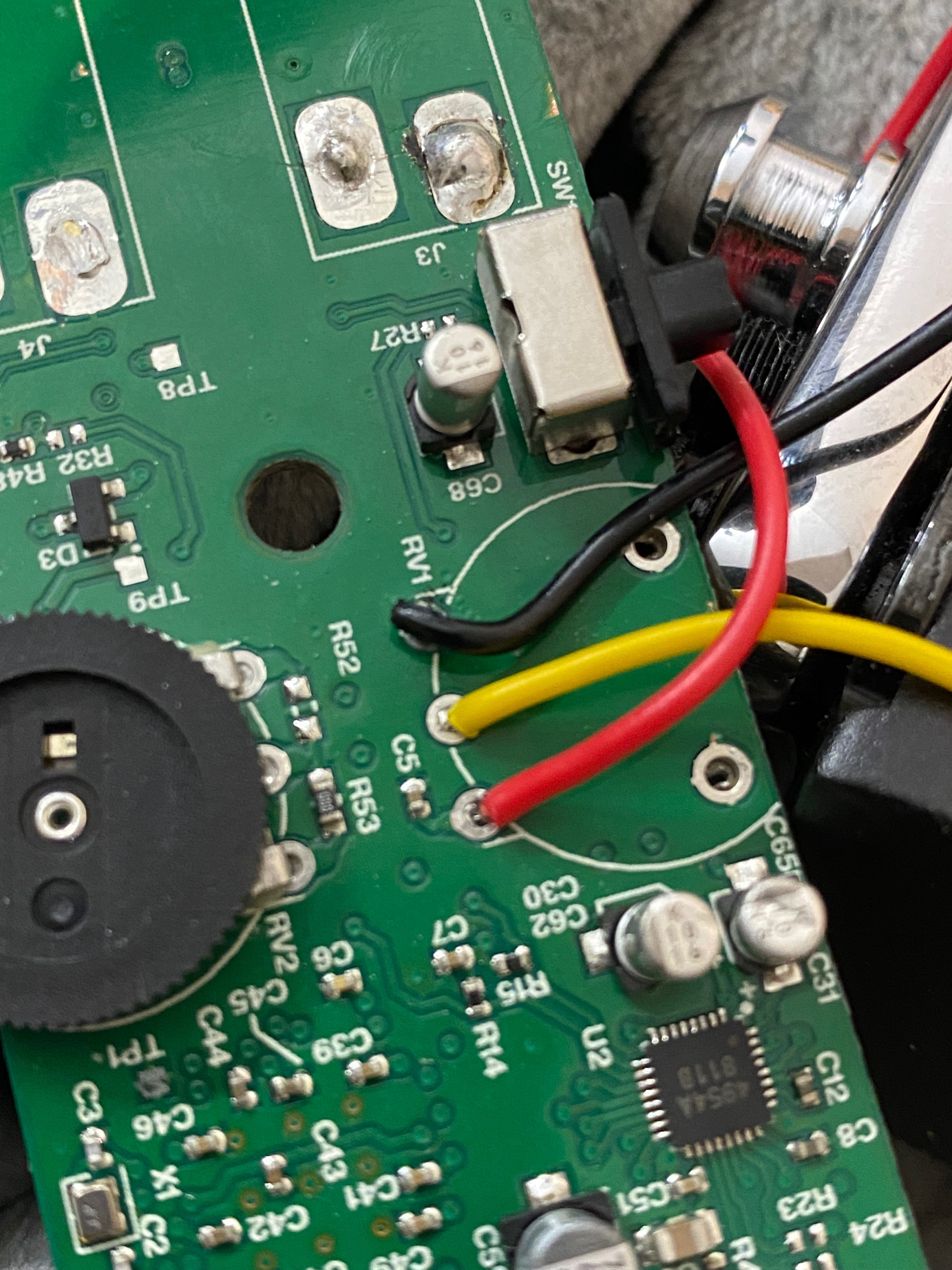
Now comes the funny part. The volume pot from the card needs to be re-placed by the already existing guitar pot. The original one is a 100k, and the guitar has a 50k, but after investigation, the volume potentiometer is not connected to any signal but to supply, and its output only goes to the 8b uC 12b SD ADC input. 12b is not enough for audio but it is good to process a DC input representing the volume. Then the uC informs the codec that provides gain control.
The datasheet of the Cypress (infineon) Cy8C32 can be found here: https://www.infineon.com/dgdl/Infineon-PSoC_3_CY8C32_Programmable_System-on-Chip-DataSheet-v28_00-EN.pdf?fileId=8ac78c8c7d0d8da4017d0ec7aa5b3f68
The audio section is build around a 32bits stereo codec, the AK4954A from AsahiKASEI. The datasheet can be found here: https://www.akm.com/content/dam/documents/products/audio/audio-codec/ak4954aen/ak4954aen-en-datasheet.pdf The chip does AD and DA conversion together with the headphone amplifier.
One trace is cut close to the led, the 2 black electrolytic caps close from the connector needs to be removed, and 3-pin connector re-used:
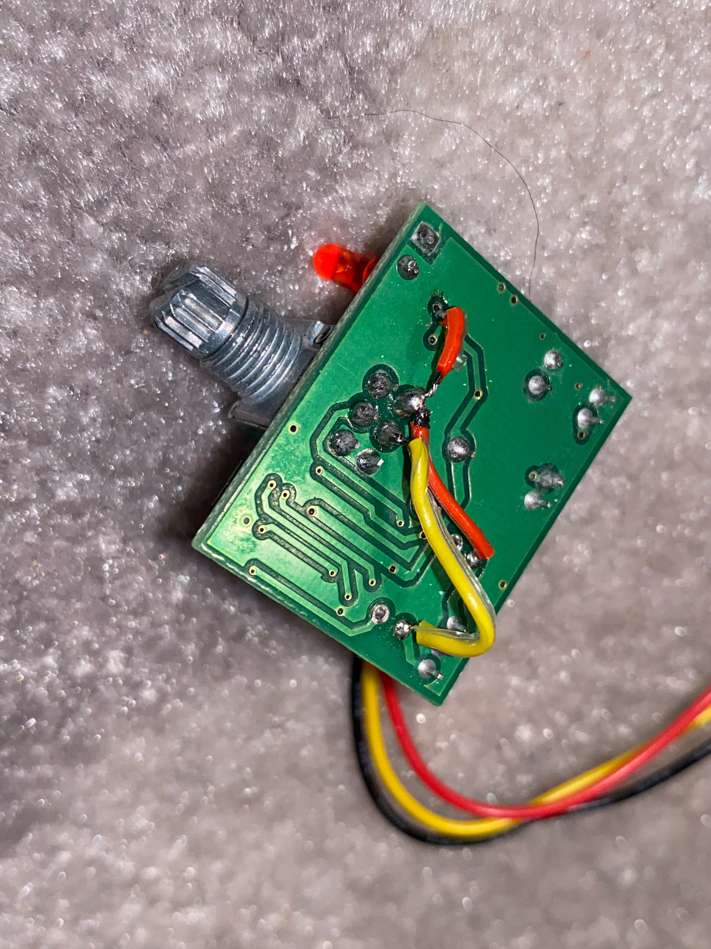
Cut PCB line (zoom on image):
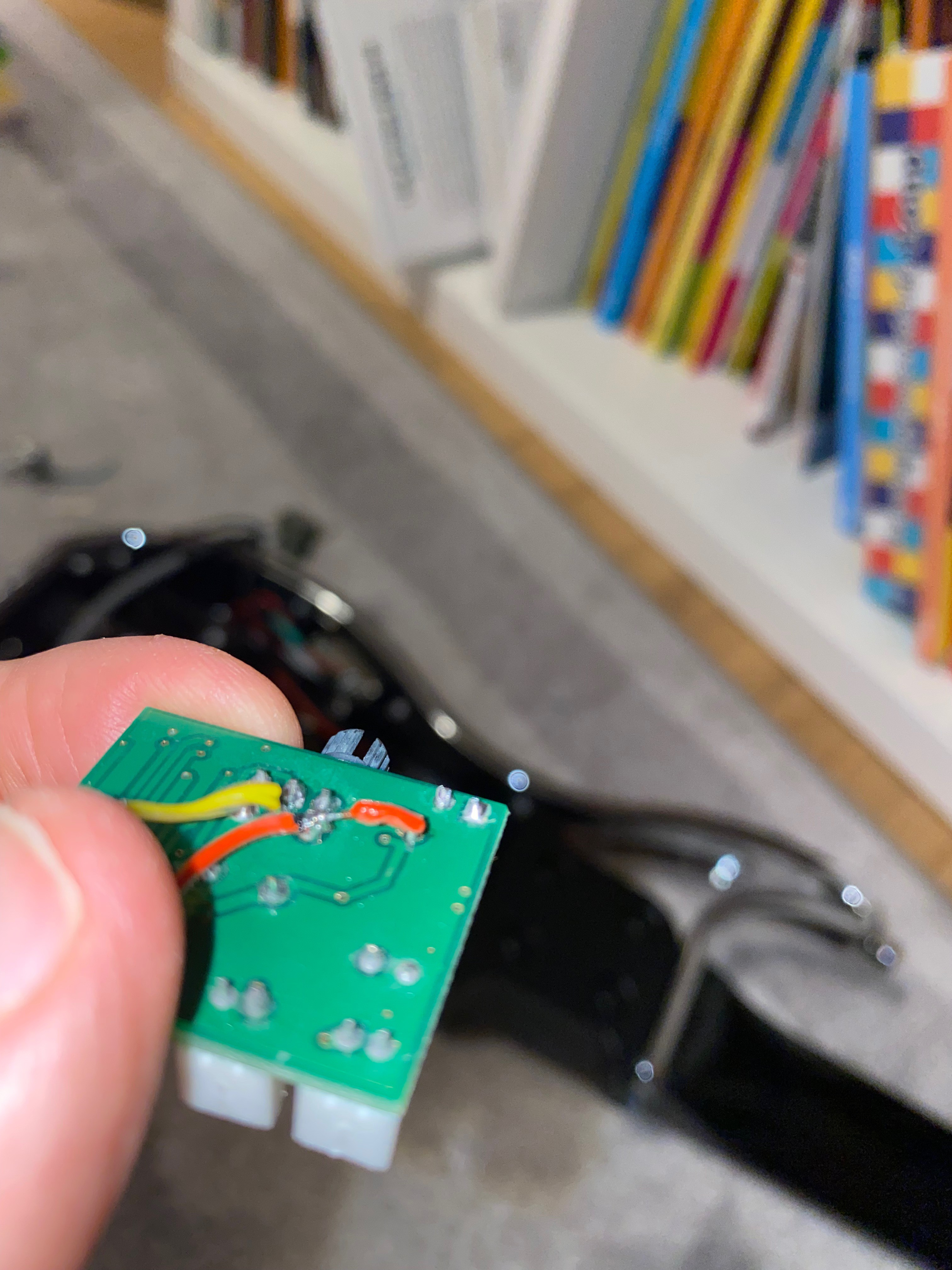
External pot wiring (after initial pot removal):
Then the 2 jack connector needs to be removed and replaced by small shielded audio cables, and the PCB is filed in order to fit without forcing:
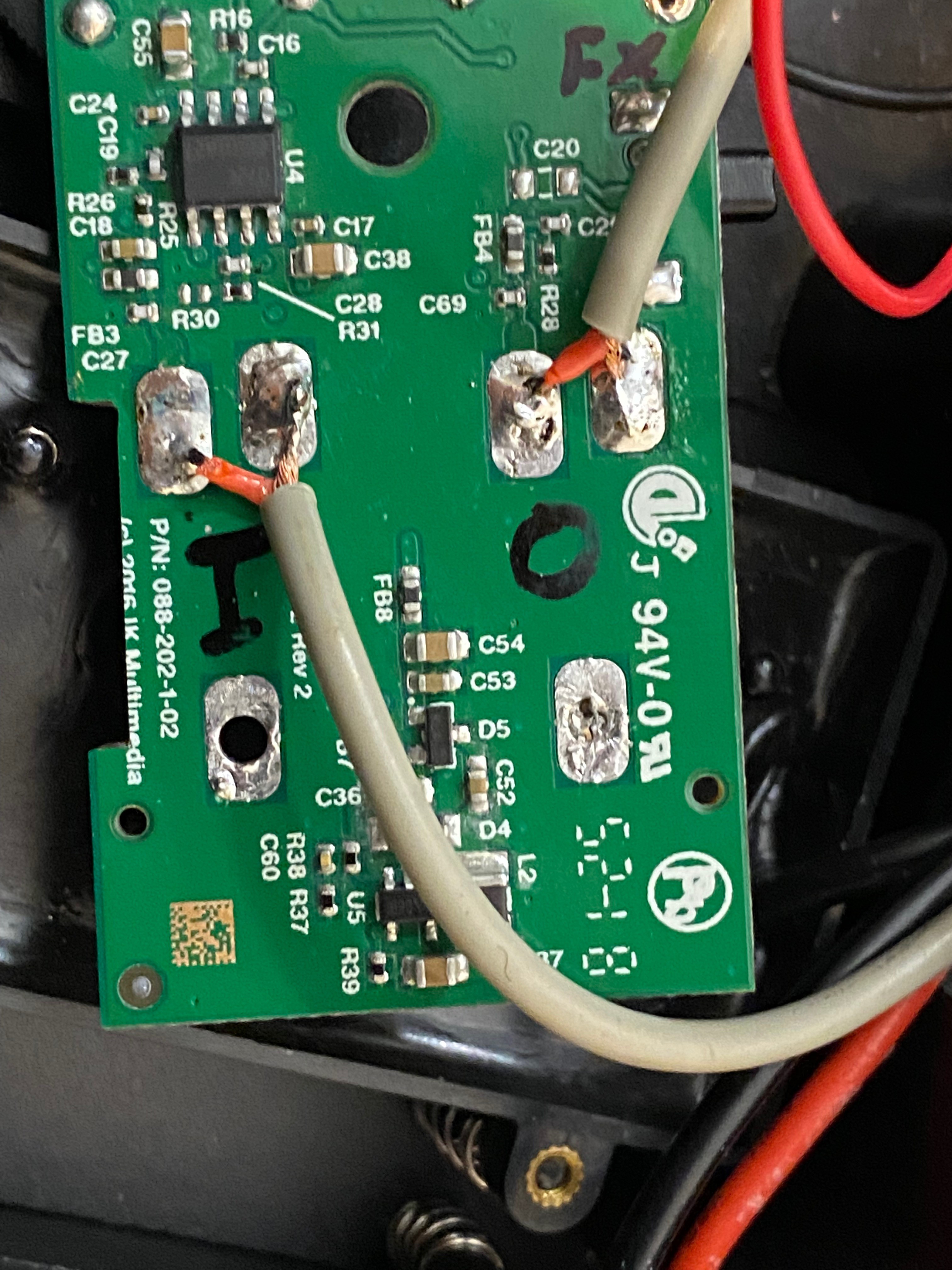
This part of the PCB (left part on the pic) only has 4 layer of ground, which explain why it can be etched, but please check before, better safe than sorry!
I initially used a cheap stereo cable for input output routing... What a BIG mistake! With the capacitive coupling within the 2 lines sharing the same shield, the coupling is large enough to turn on instabilities due to the pre-amp gain. The sound was awful with a high freq tone (similar as Larsen). With two cables, everything works fine.
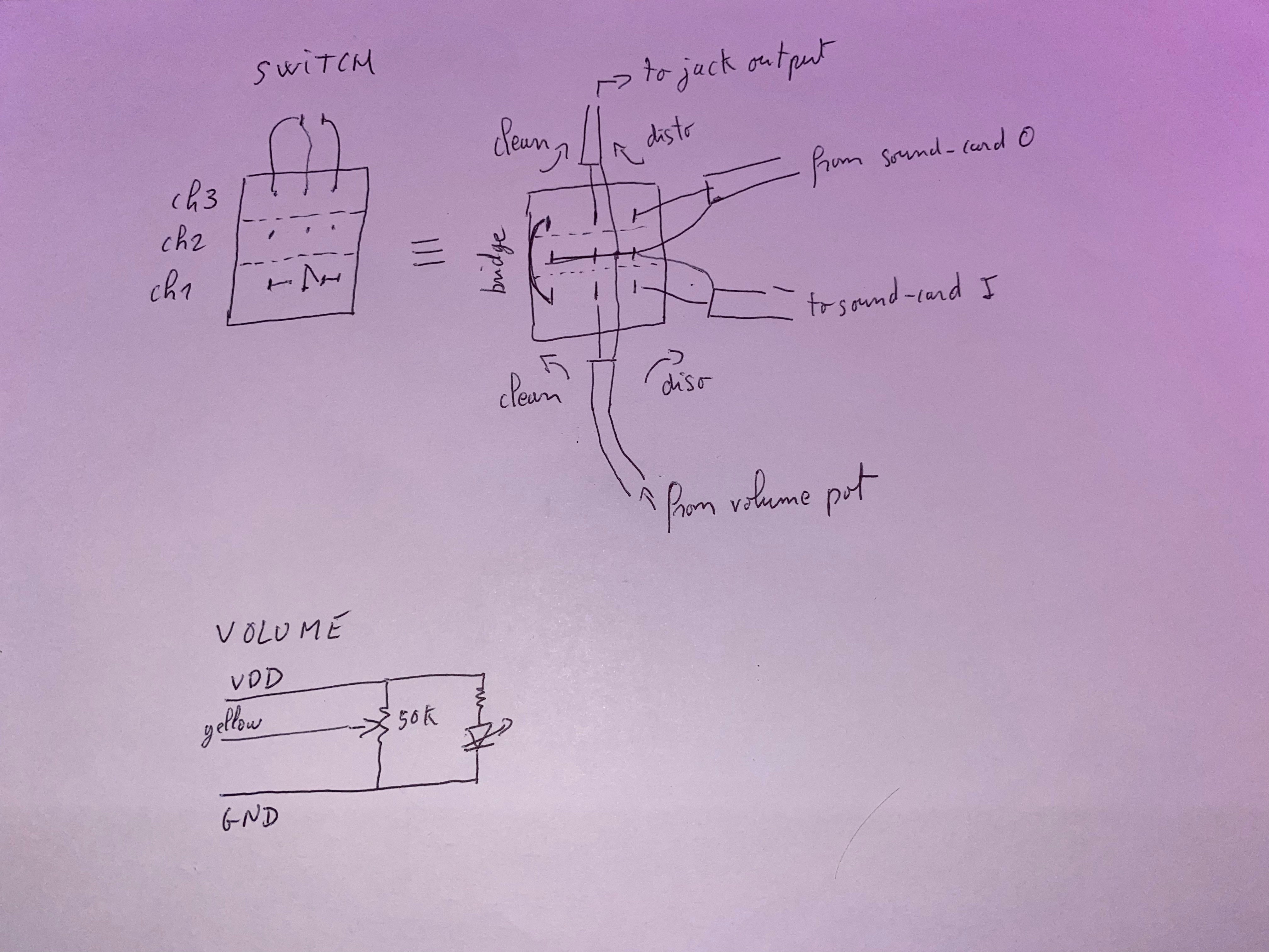
There are many possibilities to make the switching between the direct clean tones and the processed one, but I had a triple 2 ways switch (3x3=9 pins), so I used it (the interface has also a switch that could be used instead). Only 2 channels of the 3 are used. Please note that clean and disto sounds are selectable by this switch only when the classical jack 6.5mm is used to conned the guitar to an amp. Clean tone are still available with headset, but through the app.
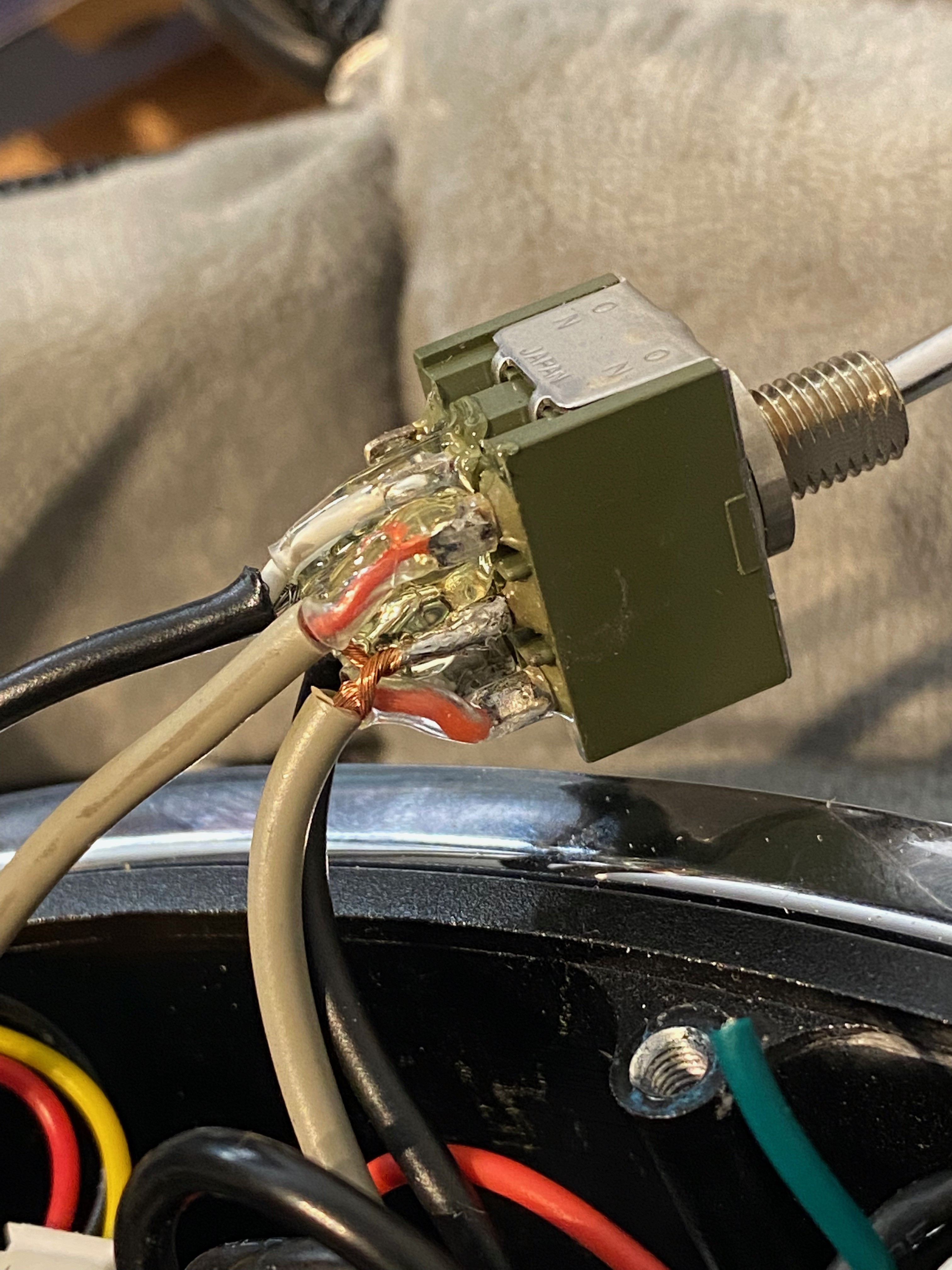
All my apologies for the glue I put ... before taking the shot.
I wish I could make better schematic... The un-used channel 2 is shorted and helps connecting the grounds together. I know the craziest theories exists about "ground loop" and will not debate on the best possible ground connections, but connecting the 4 shields together at this point is a good compromise.
Then the back of the PCB including the etched region is isolated with 2 layers of capton tape:
Then I glued the sound-card PCB to the plastic covering the usb and jack connectors. You might...
Read more »
 core weaver
 Stephan Martin
 Christoph Tack
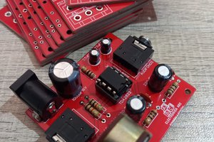
 ElectronicABC