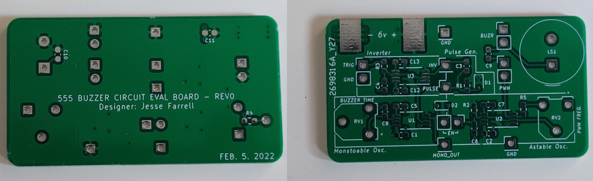
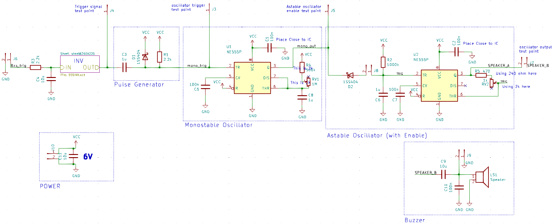
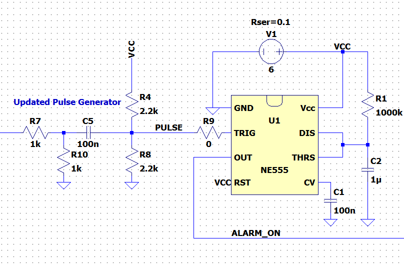
The buzzer circuit schematic and pcb are shown below.
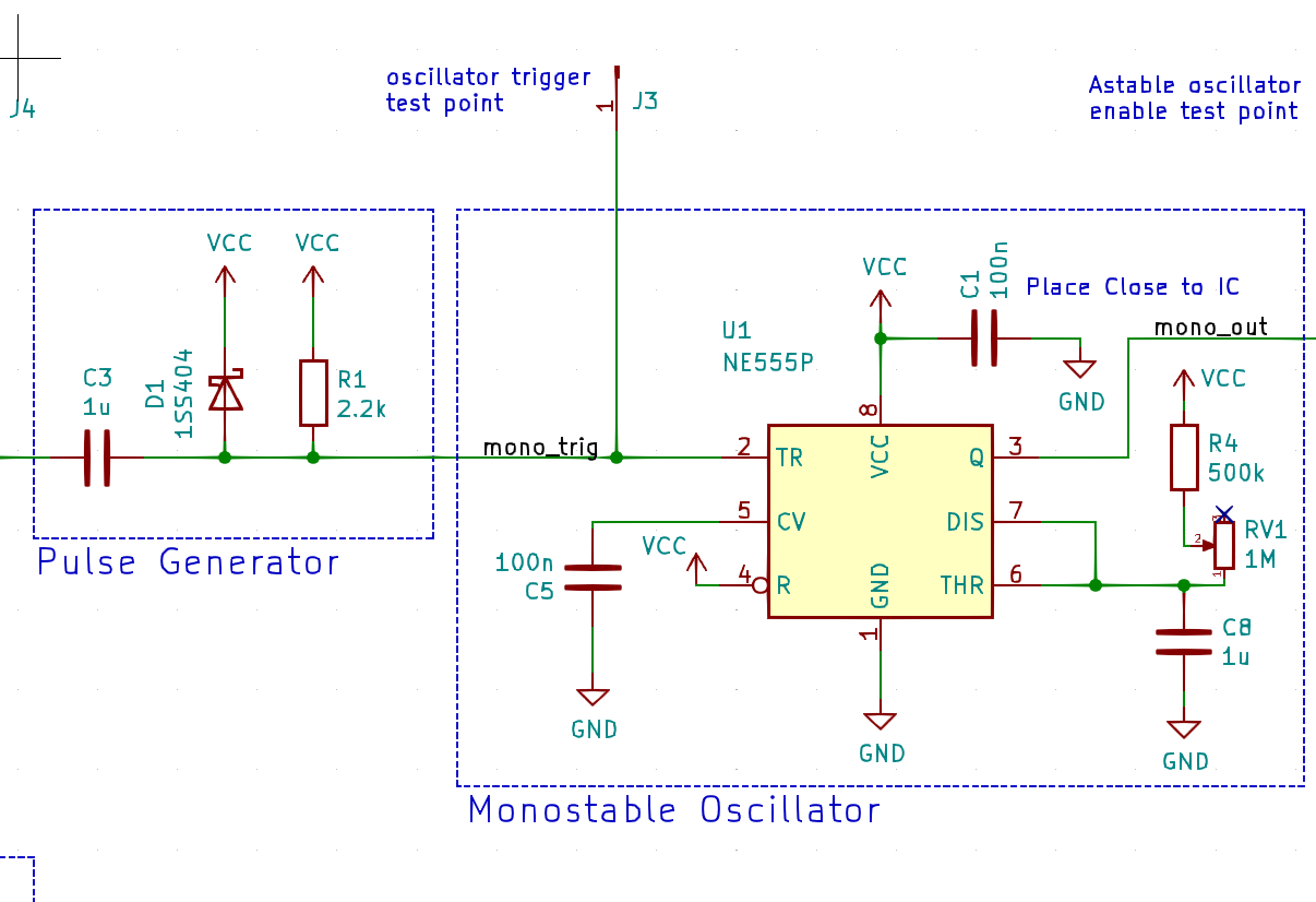
This circuit worked well for several minutes, but then began to misbehave. After about a minute of operating (20 or so triggers), the input of the monostable oscillator labeled “mono_trig” (pin 2 of U1) would vary wildly, or was pulled to ground for extended periods of time. A zoom in of the problem area is shown below.
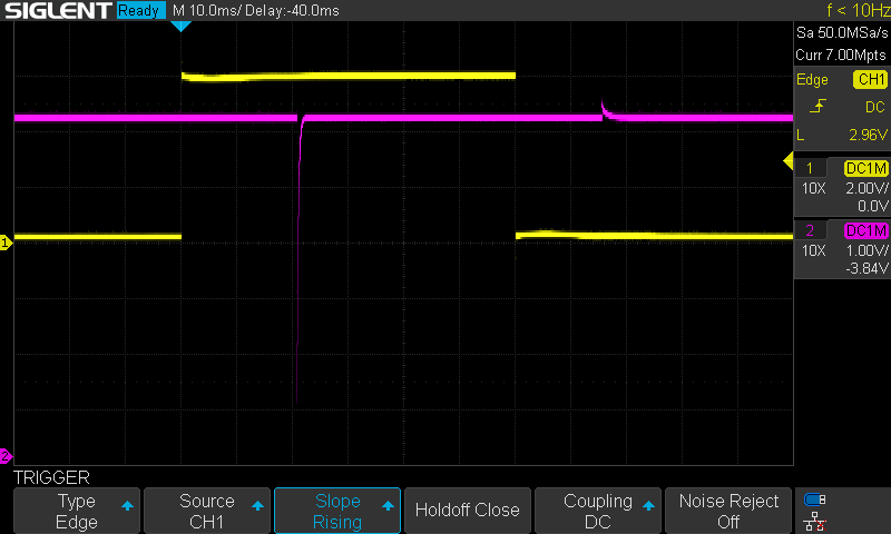
Long story short I believe I was frying my monostable oscillator with an overvoltage on the trigger pin. Below is a capture of the circuit working, shortly before it died. Channel 1 is the input waveform, and channel 2 is the output of the pulse generator (mono_trig net). Notice there is a slight peak after the falling edge of the input, I’m suspicious my scope is missing the true peak here due to the BWL of my system.
My workaround circuit is shown below. The input signal is attenuated by -6dB (*0.5), then ac coupled to a new voltage at ½ VCC. Now the voltage at “mono_trig” should be ½ VCC ± ½ VCC, so there’s no need for the flyback diode.
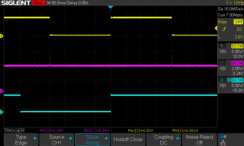
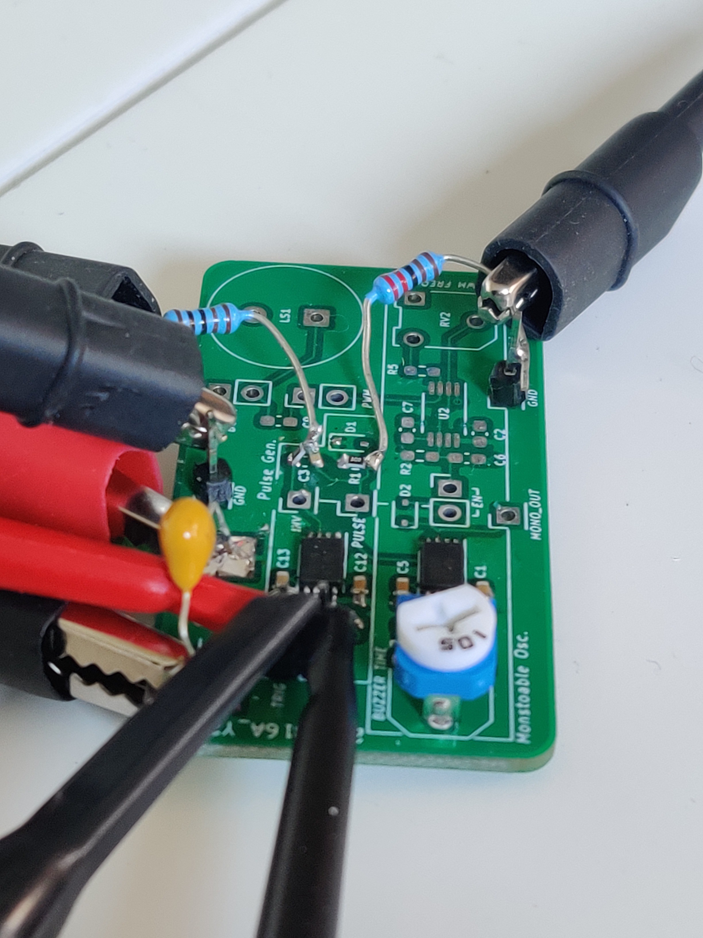
After these changes were made (see pcb below for the botch job) the circuit worked as intended. Channel 1 is the input signal, channel 2 is the output of the pulse generator, and channel 3 is the output of the monostable oscillator. Note the max voltage of channel 2 is well below 6V, and the 555 only triggers on the rising edge of the input signal as desired.
Discussions
Become a Hackaday.io Member
Create an account to leave a comment. Already have an account? Log In.