Close
0%
0%

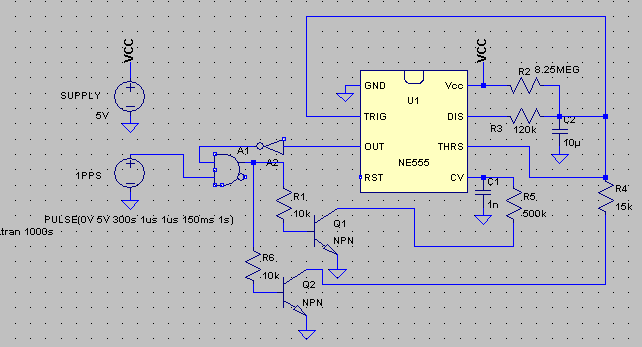
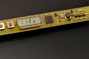
GPS disciplined 555 clock

Can we make a precise clock with analog indicators driven by 555s?

Similar projects worth following
Today, we have incredibly precise timing sources at our fingertips, delivered via GPS or internet through wireless virtually everywhere. In this project, such precision time source is combined with the venerable 555 to display time as seconds, minutes and hours, on 3 analog meters.

This is of course a silly idea, as there are so many better ways to accomplish this task. This is why it's a submission to the 555 contest under the "Shouldn't have used a 555" marquee.

This project aims at exploring the idea to depth, and make a detailed design of one particular incarnation. It would be infinitely fun to actually build it and tackle the real-world obstacles, but there are only that many hours a day, and there are jobs to be done and bills to be payed...

This project is documented using the "log" feature of hackaday.io, to provide individual chapters. Read it from oldest to newest for the logical ordering.

  • 6. Making things even nicer (future directions)

    Jan Waclawek01/10/2022 at 01:59 0 comments

    Once the whole clock is up and running, there may be several things to tweak or at least think about.

    The nonlinear nature of the output can be mitigated, if the simple charging resistor is replaced by a constant current source. A simple current mirror should suffice, to supply around 300nA into the capacitor.


    The design, as it is now, results in continuous movement of the indicators. One could argue, that moving the indicators stepwise - i.e. making seconds/minutes/hours "jumps" - may be visually nicer. This again can be accomplished by further modifying the charging circuit, so that it delivers current in pulses. This might involve additional 555 for each stage in a monostable arrangement, to provide a well-timed pulse for each stage, however, the resulting complexity will significantly increase and the basic functionality may be harder to achieve. Also, in the hours stage, leakage might cause the indicator to move slowly downwards between the jumps.


    In free-running mode (i.e. withouth 1PPS signal, when GPS module is out of lock) the current design of seconds stage results in nominally 59.45s+1s=60.45s period. This is around 7500ppm - given the inherent error is half that much, this is not entirely terrible, but not great either, and can be improved by a small trick. This lies in trimming the charging resistor R2 so, that in free-running mode it results in a nominal 60s period (consisting of 59s charging and 1s discharging); and adding a small circuit, which from the "synchronous reset" pulse pulls down pin 5 of 555 through a suitable resistor. Pin 5 is output from the 2/3 VCC point of the 3-resistor divider providing reference to the comparators, so by pulling it slightly down, the discharge cycle runs "deeper" than normally, resulting in a slightly longer charging cycle. The nominal values of the resistor divider depend on the 555 variant - the "classic" variant has a 5k/5k/5k "ladder", whereas the low-consumption CMOS variants tend to have cca 10-20x higher values; so the "tweaking" resistor has to be adjusted according to given 555 variant so, that in synchronous mode (or with the "tweaking" resistor forcibly pulled to ground) the charging part lasts nominally 59.45s.

    In this diagram, the "tweaking" circuit consists of Q1 and R5:

    Below is comparison of free-running (top) and synchronous (bottom) modes (free-running charging duration is not adjusted to exactly 59.00s, as the discharge duration is slighly off, too). Cursors are set so, that in Diff Horz duration of charging can be seen, and Cursor1 Vert indicates the bottom of discharge, i.e. the nonshifted/shifted 1/3 VCC reference value (green is voltage on capacitor, blue is scaled output on pin 3):


    It takes cca 10mV change of the 1/3 VCC reference (i.e. 20mV shift at pin 5) to change the charging time by cca 300ms.

  • 5. Setting time

    Jan Waclawek01/10/2022 at 01:20 0 comments

    A clock needs also some method to set it to the current time.

    Here, we could simply add two normally-off switches/pushbuttons(/relay contacts) to each stage's capacitor, each connecting the capacitor through a suitable resistor to 1/3 VCC and 2/3 VCC respectively, for discharge (adjust down) and charge (adjust up).

  • 4. Making things nice - output amplifier

    Jan Waclawek01/10/2022 at 01:17 0 comments

    Voltage on the capacitor swings between 1/3 VCC and 2/3 VCC. To utilize the full swing of an analog meter, this needs to be amplified and shifted, so that the output waveform starts at zero. We need to use an amplifying stage which won't load the capacitor, anyway. Utilizing a JFET-input opamp (e.g. the venerable TL07x), the load is in the range of tens of pA, mostly negligible.

    Following is an example shift-and-amplify circuit, resulting in full 0-VCC output swing:


    and the resulting waveforms (green is voltage on C2, blue is voltage on opamp's output):

    It is true that the rising portion of the waveform is not strictly linear, but this probably won't pose any problem - the difference is small, and the ticks/marks on the meters can be drawn with non-uniform spacing to match the true waveform.

  • 3. Cascading further - hours

    Jan Waclawek01/10/2022 at 00:55 0 comments

    The hours stage is virtually identical to the minutes stage (with its "synchronouos discharge" being controlled from the inverted-pin3 output of minutes stage, providing a 1-pulse-per-hour (1PPH) signal), except the "capacitor multiplier" has to provide a 60*12 (or 60*24) multiplication.

    This means, that charging current to capacitor drops below 1nA and self-discharge of the capacitor (characterized by its "intrinsic" RC constant of >100ks) becomes significant (12h = cca 50ks). Assuming the self-discharge is consistent, this can be compensated for by increased charging current (decreased R2), but this has to be adjusted experimentally, and there's probably no other way to do this than simply to log the output voltage for the whole 12h/24h, then trim R2, repeat and rinse.

  • 2. Cascading - minutes

    Jan Waclawek01/10/2022 at 00:30 0 comments

    The circuit to display minutes is cascaded to the seconds stage (which effectively provides a 1-pulse-per-minute output, 1PPM), and based on the same principle - it should charge the capacitor while ignoring the first 59 1PPM pulses, and reset itself upon the 60th pulse.

    There are differences, though:

    • parts used in the charging RC in the seconds stage were rather at the edge, as was the resulting current into capacitor. Here, we need 60x longer RC, so we need some trick, possibly increasing capacitance 60-fold, without the associated increase in parts cost.
    • we don't need free-running oscillator operation, as the seconds stage provides free-running timebase (albeit inprecise) for the case of GPS not outputting the 1PPS signal (which GPS modules tend to do when they don't have a lock). All we need here is that for the first 59 seconds the output is low, and then it goes high. Also, a 1-minute "runback" of the indicator asociated with free-running discharge wouldn't be nice.
    • the output from the seconds stage (which we take from the pin 3 (inverted), so that we have 1PPM for both synchronized and free-running seconds stage) may be as short as 100ms (or somewhat shorter, if the "synchronous discharge" resistor in the seconds stage is adjusted not entirely correctly); the "synchronous discharge" circuit in minutes stage has to take this into account.

    The first issue can be solved using an opamp-based "capacitance multiplier". In the linked circuit, choosing R2=R3=1kOhm and N=60 allows to use the same 10uF capacitor, while the entire circuit presents to its input an equivalent of R3=1kOhm and C=600uF. The 1kOhm value is negligible compared to the charging resistor of several MOhms.

    The second issue is solved simply by disconnecting the discharge output (pin 7) from the capacitor.

    The third issue is solved by connecting the "synchronous discharge" circuit not to the "virtual - multiplied" capacitor, but directly to the real capacitor itself. The discharging resistor is adjusted so that the discharge happens below 100ms, but slowly enough so that the 555 can cut off the discharge process as soon as the capacitor's voltage drops below 1/3 VCC. This is the modified circuit:

    and following are the simulated waveforms (green is voltage on the "virtual capacitor" i.e. on TRIG and THRS pins of 555, red is simulated 1PPM signal from seconds stage, blue is output of pin 3 of 555; note, that 1 hour is 3.6ks):

    R2 has to be trimmed so, that nominal duration of 1 on output on pin 3 is 59.5 minutes, again, this provides tolerance for the cca 7500ppm temperature-induced error.

    Charging C3 for a hour - rather than for a minute in the seconds stage - means 60x less current flowing into it, i.e. a few nA instead of 200-400nA. Isn't it a problem with the leakages of connected comparators/output circuitry then?

    The problem is here slightly different: here, only leakage of the opamp applies directly to C3 (and also leakage of the "synchronous discharge" circuit, which has to be designed carefully in this regard). Charging current through R2 is still in the 200-400nA range, and it's the nature of the "capacitor multiplier" circuit, that most of the current from the "virtual capacitor's" input flows into the opamp's output, and only fraction of it into the real capacitor itself. So, the leakages on the "virtual capacitor" (i.e. leakages into TRIG and THRS, and also into opamp which will be added for the output to indicator) have to be compared to this 200-400nA current, thus are mostly negligible.

  • 1. Back to the project: The seconds stage

    Jan Waclawek01/09/2022 at 23:46 0 comments

    We have established that a 555-based timer is not precise enough as a timebase for a clock. So, let's employ a readily available precise clock source: a GPS receiver. Most GPS modules provide a one-pulse-per-second (1PPS) output, usually with user-adjustable pulse width.

    Now the challenge is to use this signal to discipline a 555, which will provide the signal driving the analog indicator (meter).

    To indicate seconds, the 555 is to be used in the basic datasheet-given astable operation, where the resistors are chosen so that capacitor is charged through most of 60 seconds of a minute, and then relatively rapidly discharged. Voltage of the capacitor is amplified and output to the meter.

    To utilize the 1PPS signal, the circuit has to reject somehow the first 59 pulses, and then use the 60th pulse to synchronize the astable process. So let's adjust the charging RC circuit so, that it charges the capacitor for 59 seconds, and then discharges it for 1 second. Visually, on the indicator, the 1s "runback" will be quite natural. Charging corresponds to the state when 555's output (pin 3) is 1 and discharging corresponds to output set to 0, so inverting this output and ANDing with the 1PPS signal provides the needed rejection of 59 pulses.

    10uF PP capacitors are relatively affordable (they cost around $5) and 8MOhm resistors are still manageable. The charging current  fluctuates between 200nA and 400nA, so as long as leakages are below the order of 200pA, this is a relatively safe arrangement. Of course, other leakages (PCB, soldering residua, etc.) have to be avoided, too.

    Would this be not viable, the charging resistance would need to be decreased and capacity increased. Capacitance multiplier can be employed for this; we won't discuss it here as it will be utilized in the subsequent stages anyway.

    The "unsynchronized" discharge through the 120k R3 provides the cca 1s discharge time. This provides both a free-running (although rather unprecise) timebase, and also a window to accept the 60th 1PPS pulse.

    To keep things nice and slow, the "synchronized discharge" is set by R4 to last cca 100ms. The GPS module should be set so that the 1PPS pulse duration is somewhat longer, say 150ms.

    To allow for the temperature-induced error, R2 has to be trimmed so, that the charging portion of waveform should last nominally cca 59.45s. This allows temperature-induced error of cca 450ms, or cca 7500ppm, which compared to 3000-4000ppm from our initial analysis allows for a bit more leeway for various sources of errors.

    Below are the simulated waveforms of this circuit (green is voltage on capacitor, red is 1PPS (scaled and shifted), blue is output on pin 3 of 555 (scaled):

    Below, the same waveform, zoomed, shows the slower "free running" in the first portion of discharge, cca 200ms (R2 in our simulation was not trimmed perfectly, otherwise we would see this portion to last cca 450ms) and the "synchronized" portion cca 80ms (again R4 is not set perfectly, but that won't really change much in the working of the circuit).

  • 0. Before we start, let's talk about 555's precision

    Jan Waclawek01/09/2022 at 22:34 0 comments

    The 555 is a timer, so it should be usable as a basis for timekeeping, right? Well, it boils down to precision: centuries of evolution, nowadays we are spoiled by precision clocks, so not any timer will make the cut.

    But how precise or imprecise is a 555, anyway?

    Let's assume we want to build a 555-based 1Hz astable oscillator, using the basic datasheet-given circuit. A cursory glance at the datasheet seems to indicate, that it actually does provide a precision characteristics, Initial error of timing interval, with values (depending on particular 555 model) in around 1%-3%. That's very bad, beyond any usability for timekeeping.

    But wait a minute, there's some footnote to that value:

    Timing interval error is defined as the difference between the measured value and the average value of  a random sample from each process run.

    Okay, so this actually does not specify precision of any kind, this specifies the spread of values across individual pieces. In other words, we can work around this problem by individually trimming the external components. So what's next?

    Some 555 datasheet give a Temperature coefficient of timing interval,  with values of 50-200 ppm/°C. This is mostly given by temperature-dependent mismatch between the 3 internal resistors in the divider ladder, which determine the two thresholds between which the voltage on external capacitor oscillates. There are also temperature-dependent changes in the comparators' offsets. These are all internal to the chip and can't be effectively influenced by the user (except maybe some intricate and complex compensation schemes, e.g. building a thermostat around the circuit, which are simply not worth the hassle). Let's assume that we select a model where this coefficient is around 100ppm/°C and we operate it indoors, within a 10°C span, that gives us the baseline variation of cca 1000ppm or 0.1%.

    There is also a voltage-dependent coefficient, up to 0.5%/V, but we can easily work around this using any modern LDO with output voltage variation in the range of few 10mV as a power supply, reducing this error to below 100 ppm, i.e. negligible compared to the temperature-dependent variation.

    Another error source might stem from temperature variations of the delay between comparator and output, i.e. the internal latch's delay. This delay is in the range of 100ns, given we are going to operate in 100ms range and up, this error is entirely negligible.

    Even assuming perfect external components and the 10°C operation temperature span, the timekeeping precision of 1000ppm is disappointing. This means around one and a half minutes per day, which was the typical error of commonplace wristwatches I used to wear as a child. Modern mechanical watches and cheap crystal oscillators are good to tens of seconds in a month, i.e. few tens of ppm. So, a 555 is not a good timebase.

    But it still can be good for our purposes. We need to consider impact of external components, too.

    Resistors are quite readily available down to cca 25ppm/°C, this adds another cca 250ppm to our error budget.  Capacitors are tricky - we are going to charge them slowly in several hours (12h = cca 50ks), so we want as low leakage as possible, this implies polypropylene (PP) film capacitors. (Generally, they have leakage time constant > 100ks at room temperature, which means that we might need to compensate for leakage in the "hours" stage). They have a relatively high temperature coefficient of around 150ppm/°C - another 1500ppm to our error budget. Time constant of dielectric absorption is poorly studied, but given our long time constants it might play role in our application - luckily, PP has relatively low dielectric absorption of cca 100-1000ppm.

    The timing capacitor is also loaded by inputs of 555's internal comparators - in modern CMOS 555 variants this represents 10s of pA, inputs of any amplifiers (to provide output to indicators) - again in the realm of pA with CMOS...

    Read more »

View all 7 project logs

Enjoy this project?

Share

Discussions

Similar Projects

Does this project spark your interest?

Become a member to follow this project and never miss any updates