 LorneChrones (Nick)
Demo Video!
Premise
I heard about the 555 timer contest at the beginning of Dec 2021 and I wanted to see just how silly the 555 could be pushed. Inspired by the silliness at SIGBOVIK (especially the On The Turing Completeness Of PowerPoint project by Tom Wildenhain ), I wanted to try to answer the question "Could you make all the ingredients necessary to make a solely 555 timer (or variant) based Turing Machine?"
Early Research / Simulation / Breadboarding (Early Dec 2021 through Dec 8, 2021, give or take):
I busted out my breadboard and what TLC555s I had kicking around and looked at the datasheet to see what truth tables (and other various behaviours) could be extracted from the 555 or combinations of it. Although my implementation for this project didn't include all of my findings, I did document what other gates (I also incidentally made a boost converter with the 555's DISCHARGE pin too!) could be extracted out of a 555 along with how to construct them and their measured breadboard propagation times. All of which can be found on the project github page here: https://github.com/lambdawolflabs/555-Timer-Functional-Complete-Logic-Gates (Specifically here: https://github.com/lambdawolflabs/555-Timer-Functional-Complete-Logic-Gates/blob/main/555_Gates_Findings_12-4_and_12-5-2021.txt )
I wanted to see if I could stick as much as possible with the 555 being the sole active element, ala trying to relying upon external discrete transistors, diodes, etc (and of course no other ICs other than 555s / 556s). This led to the gates that I found / designed to be hybrid NMOS and CMOS logic. (The 555's DISCHARGE pin is just as useful as an output as the explicit OUTPUT pin!). This segment was some-what trial and error but from the breadboard I used Logi Sim's built in combinational logic solver to extract equivalent functions ( http://www.cburch.com/logisim/ ).
I learned that the Bipolar 555s are much too slow in propagation times (on the order of single digit microSecond propagation time) vs the hundreds of nanoseconds of propagation time for the CMOS 555s. This shouldn't be a surprise given CMOS has higher input impedance and lower input capacitance compared to Bipolar.
I also recreated the circuits in LTSpice to verify the logical functions and propagation times too. I only had the NE555 SPICE Models to work with, but CMOS and Bipolar 555s are functionally identical. (Full simulation directory here: https://github.com/lambdawolflabs/555-Timer-Functional-Complete-Logic-Gates/tree/main/Simulations )
From this, I decided to go with the (relatively speaking) fastest gates I had found thus far:
- Intrinsic 2 Input AND Gate (CMOS inputs, NMOS output) - Uses 1x 556 or 2x 555s
- Intrinsic 2 Input NOR Gate (CMOS inputs, NMOS output) - Uses 1x 556 or 2x 555s
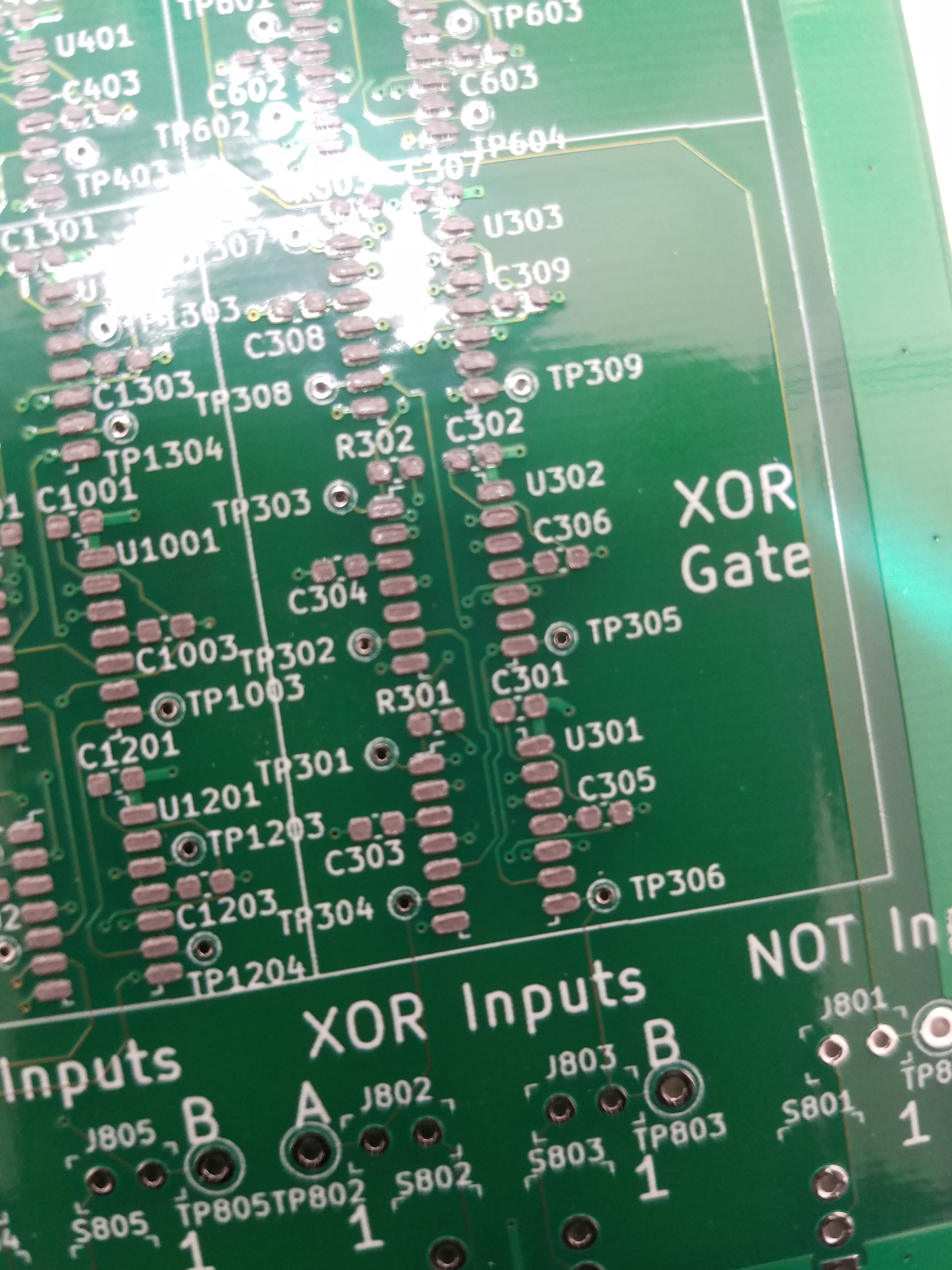
- 3x NOR Based 2 input XOR Gate (CMOS inputs, NMOS output) - Uses 3x 556 or 6x 555s
- Intrinsic NOT Gate (CMOS inputs, CMOS outputs) - Dual Inverters (556) or Single Inverter (555)
- Intrinsic Safe-RS Flip Flop (CMOS inputs, CMOS outputs) - Dual Safe-RS Flip Flops (556) or Single (555)
- Note: This is already available to the 555 so nothing amazing here.
Schematic Capture (Dec 8 - Dec 18th 2021, give or take)
I knew going into this that there was going to be alot of repeat work, both on the Schematic side and on the PCB layout side. So that meant hierarchical schematics and replicate layouts as much as possible. After some searching, I fortunately found MitjaNemec's Replicate Layout plugin tool for KiCAD ( https://github.com/MitjaNemec/Kicad_action_plugins ) which, honestly, probably made the layout possible within the timeframe of the contest. Excellent set of tools, massive kudos to them!
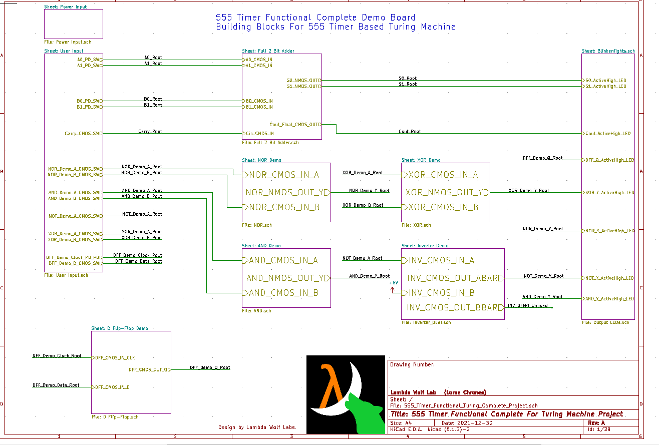
Full schematic can be found here: https://github.com/lambdawolflabs/555-Timer-Functional-Complete-Logic-Gates/blob/main/Sch_RevA_555_Timer_Functional_Turing_Complete_Project.pdf
There was a lot of checking and rechecking to make sure that the schematic seemed as readable as possible (perhaps too verbose in some spots in retrospect). KiCAD's ERC was used extensively. Re-verification was done in LTSpice and Logisim, especially for the 2-bit adder and D Flip-Flop. I then ordered what components ahead of time (with some spares) whilst I did layout.
BOM can be found here: https://github.com/lambdawolflabs/555-Timer-Functional-Complete-Logic-Gates/blob/main/BOM_RevA_555_Timer_Functional_Turing_Complete_Project.csv
PCB Layout Capture, DFM and Ordering (Dec 18 2021 - Dec 31 2021):
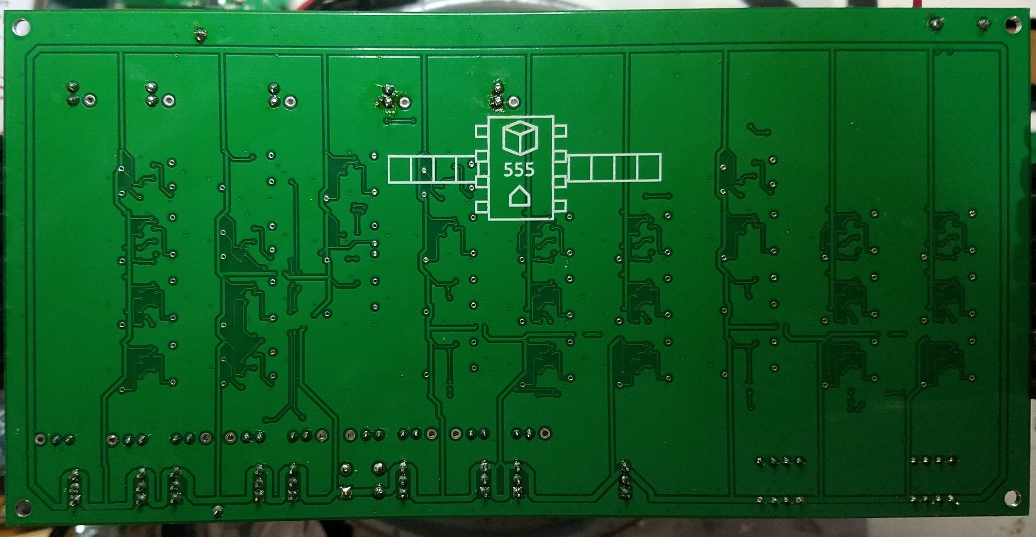
After several verifications, I started the layout in KiCAD. I wanted it to be as cheap/easy to build as possible so I opted for 2-layer stackup with 6mils / 6mils design rules exactly like OSHPark's 2-layer service ( https://docs.oshpark.com/services/two-layer/ ). After setting up the design rules, I went to work with the rough board area study (where I wanted to place the blocks, etc). After being happy with that I then placed/routed each smaller gate (AND, NOT, XOR, NOR) as the template to use with MitjaNemec's replicate layout tool.
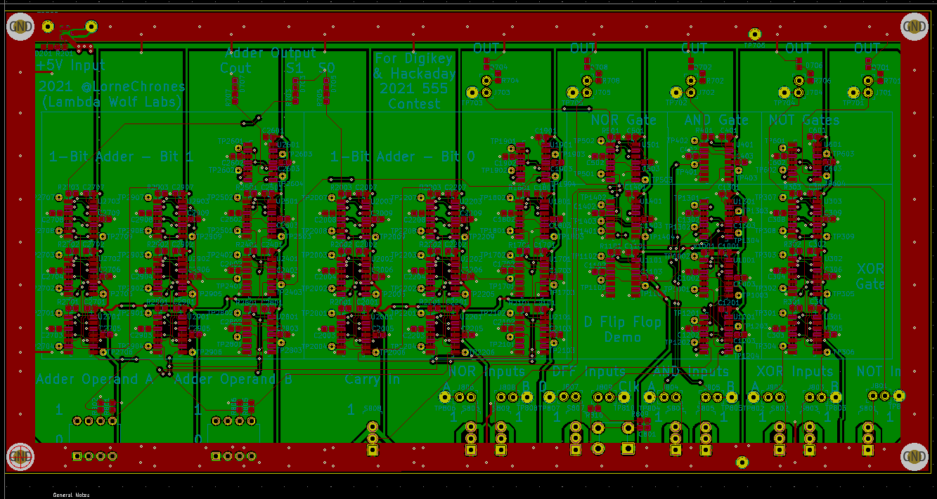
After completing layout (and running down DRC errors and warnings), I submitted the gerbers to an online service for automated DFM/DFA valor check to make sure there wasn't anything blatantly bad. With a clean bill from the DFM/DFA I ordered the board through PCBWay on the 31st (whew!).
Gerbers can be found here: https://github.com/lambdawolflabs/555-Timer-Functional-Complete-Logic-Gates/blob/main/Gerbers_RevA_555_Timer_Functional_Turing_Complete_Project.zip
PCBA PDF (All layers) can be found here: https://github.com/lambdawolflabs/555-Timer-Functional-Complete-Logic-Gates/blob/main/PCBA_PDF_RevA_555_Timer_Functional_Turing_Complete_Project.pdf
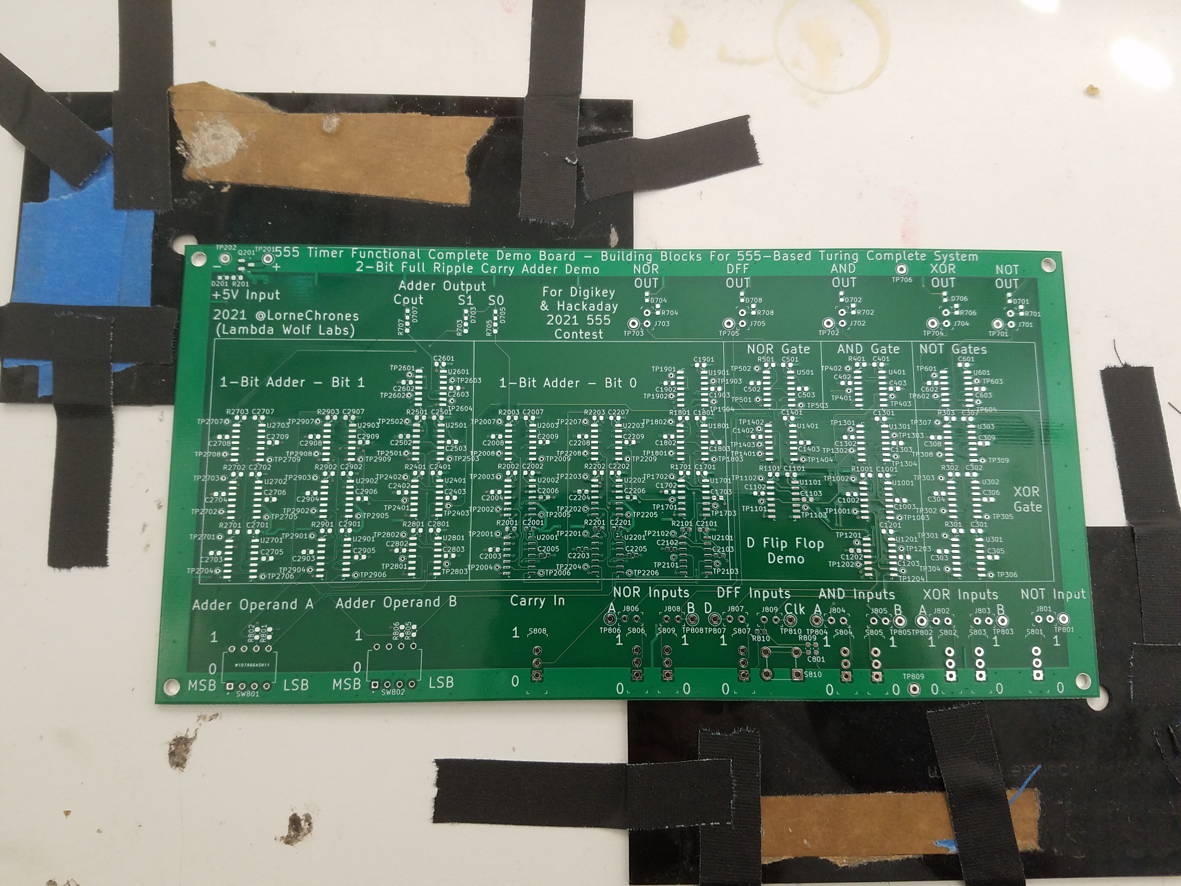
Boards Arrive, Assembly, Bring-Up, Demo & Submit (Jan 7 - Jan 9th 2022):
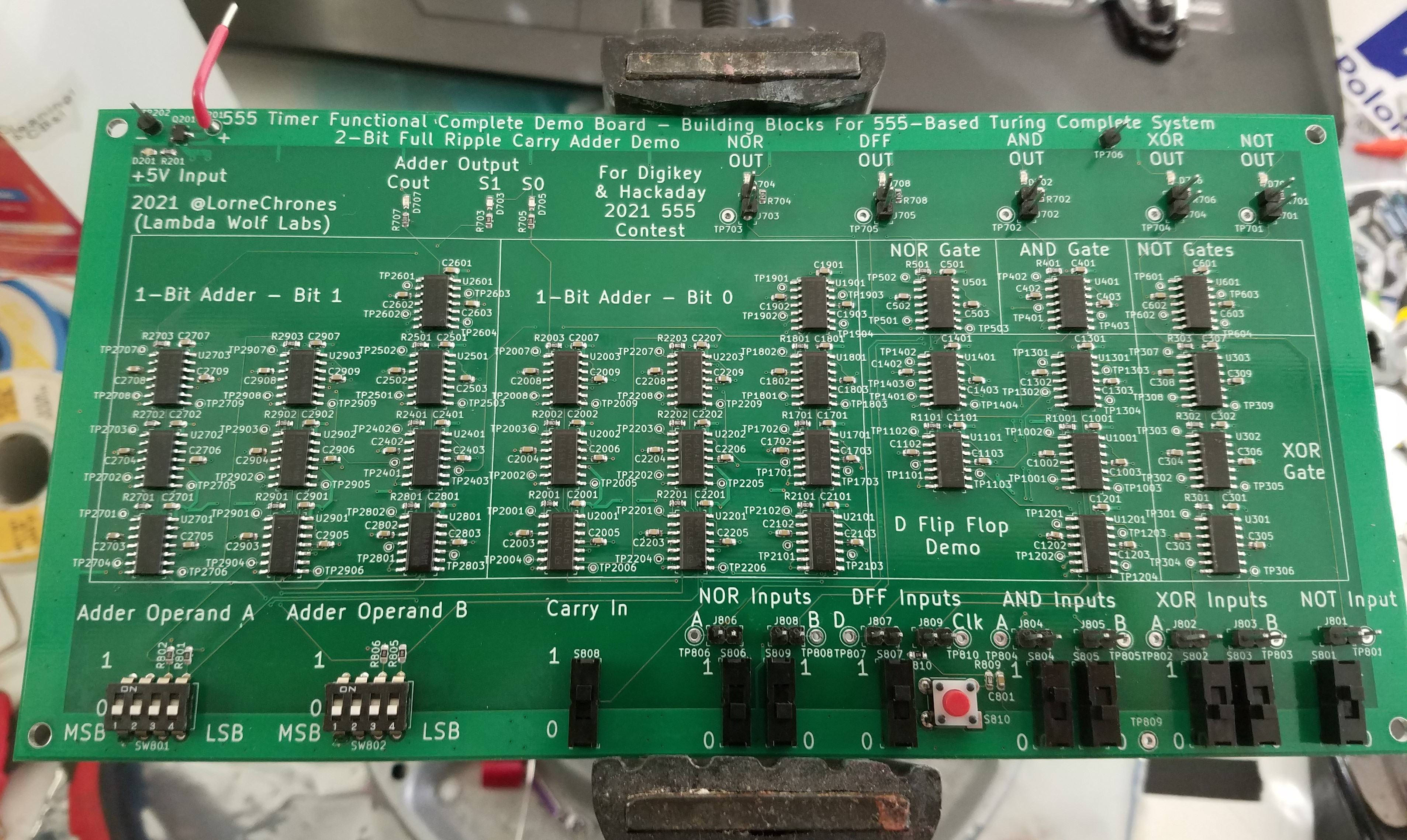
Happy New Year! The boards arrived and I immediately went to assemble. After applying solder paste (I ordered a stencil as well) and hand placement of the SMT parts, it went in my toaster oven for the usual SMT reflow cycle. Afterwards I inspected it, hand reflowed what paste/solder balls remained with my reflow station and then cleaned up the board with pure IPA + Flux Cleaner + Toothbrush. I soldered the remaining TH parts to the board and then performed bring up.
One visual inspection, open/shorts/diodes check with the DMM, the usual song and dance later, the board was ready to go! I powered up the board (~100mA idle current at 5VDC) and verified all the functions worked!
I then performed propagation tests with my scope and sig gen on each of the gates (and the D-FF), all my results have been posted here: https://github.com/lambdawolflabs/555-Timer-Functional-Complete-Logic-Gates/tree/main/Propagation%20Times%20Scope%20Shots
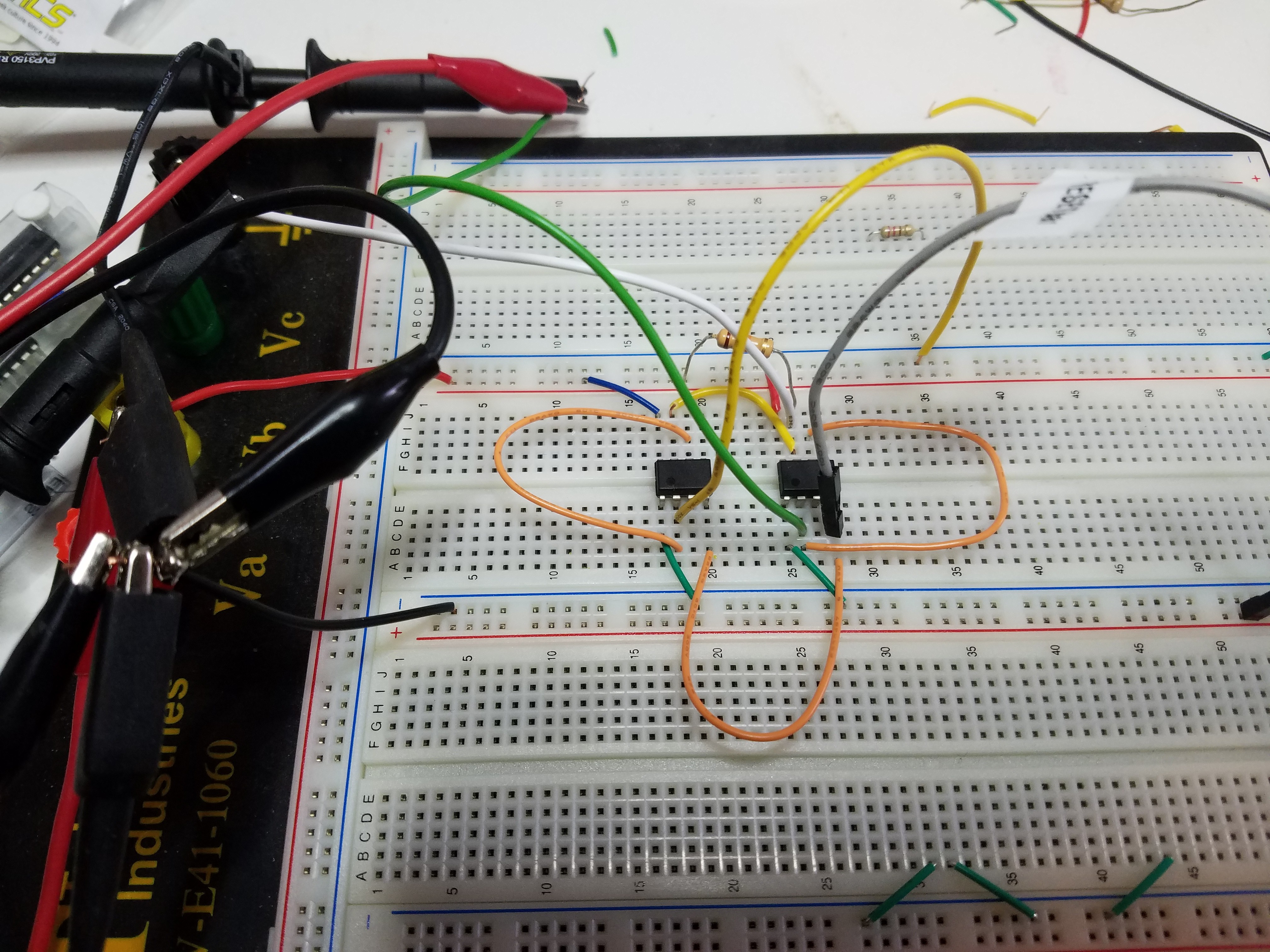
The jumpers were specifically included in order to minimize as much parasitic input/output capacitance to make the propagation measurements as true as possible:
Here's the setup when testing the propagation of the NOT gate. The red alligator clamp was from the sig gen:
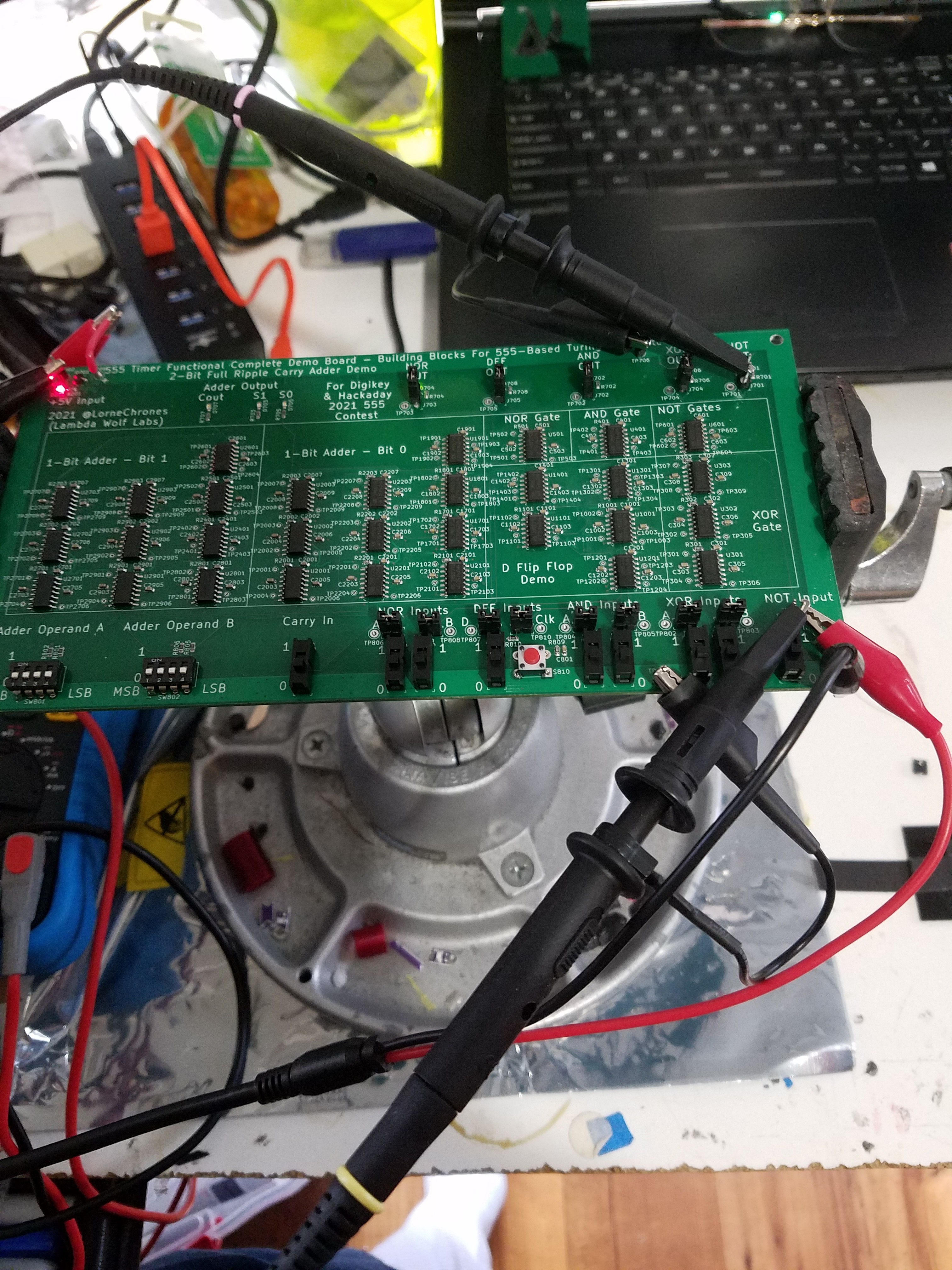
I used a Rigol DS1054, Rigol DP832 and a BK Precision 3011. The board was running at 5V in a ~20C ambient room temperature.
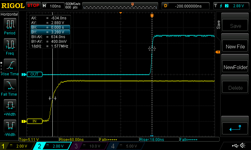
Overall for simple gates (e.g. the NOT gate or the AND gate) I was measuring on the order of 150nSec to 200nSec input to output propagation time.
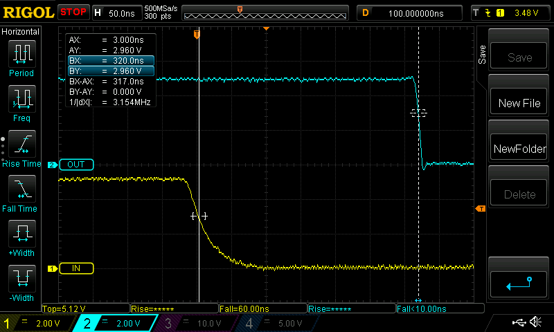
For most of the gates, the propagation time was symmetrical (1->0 and 0->1) however for the NMOS based gates the falling edge was, understandably, faster than the rising edge. Even with a relatively low 1kOhm pull up resistor (these NMOS pull ups were a significant contributor to the static power consumption of the board).
More combination gates like the XOR or the DFF had longer propagation times with the DFF having the longest of ~650nSec.:
Finally here's the demo video!
I believe it's technically (maybe not practically!) achievable to build a 555 based microprocessor / Turing machine using the ingredients / building blocks demo'd here.