 bornach
Let's abuse some 555 timer ICs!
Consider two 555 timers configured in monostable mode
Now it would be nice if the 2nd monostable could be triggered automatically after the first one has reset. We can accomplish this by using a 100 nF capacitor to link pin 3 of the first 555 to pin 2 of second 555. If I trigger the first monostable, when it resets itself the second monostable will be triggered.
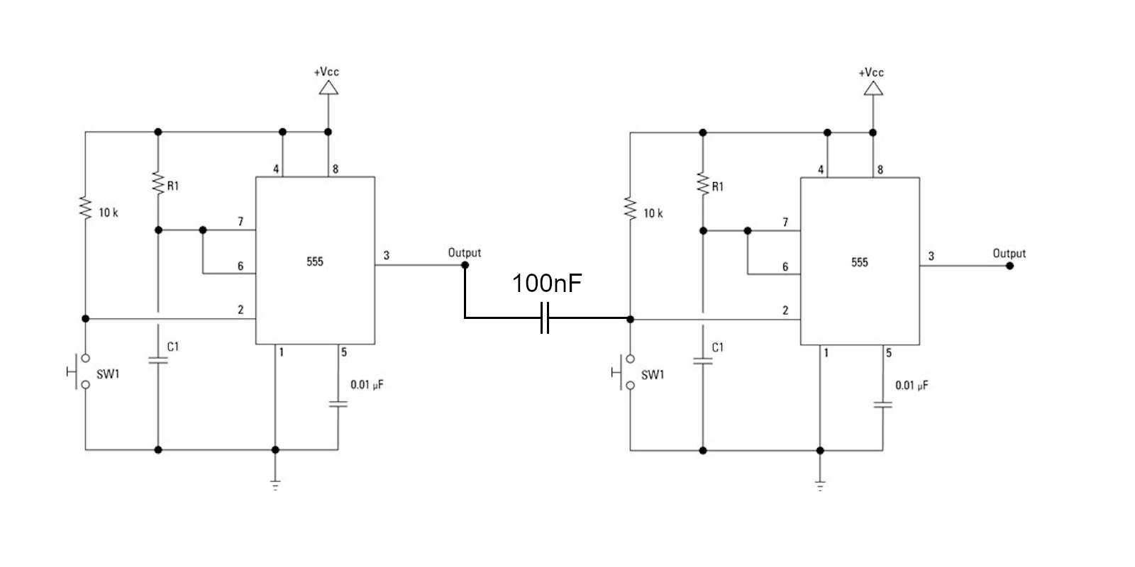
The exact capacitance to use in the link will depend on the other component values in the circuit and the type of 555 timer IC being used. I'll be using NE555 chips.
We can extend this chain to arbitrary lengths. I shall begin by chaining 4 monostables in a closed loop, so they continuously trigger each other as if passing an active token in a ring.
For obvious reasons you should not use 555 timers this way. There is no guarantee that exactly one monostable will be active -- there might be more than one on power up, or none at all. Momentarily grounding pin 2 of one of the 555s will initialise the chaser circuit properly.
This is why it is far better to use a CD4017 IC with a 555 in astable mode for this application.
Since loading down pin 3 will alter the capacitance and risk losing the token, we are limited to using this sequencer for blinking some LEDs in an attractive way.
I tried animating a green walking man but I really suck at flip book animations.
We can introduce more 555 timers to act as buffers. To avoid loading down pin 3, the 2nd row of 555s are connected to 10K pull-ups and pulled to ground by pin 7. This configuration also allows us to level shift. The top row of 555 timers are on a 5V rail while the bottom row of 555 timers are on a 12V rail.
Why would we want to do this? We can now use this circuit to drive a 12V bipolar stepper motor. The NE555 can drive up to 200mA.
Again for obvious reasons you should not use 555 timer ICs to drive motors. They lack the current limiting safety features of proper motor drivers. Were I to physically stop the motor from turning, the back EMF will drop to zero and most of the 12V supply will be dropped across the NE555 current drivers on pin 3, and risk damaging the chip.
So I've just demonstrated how to abuse a bunch of 555 timers to sequence some blinking LEDs and to spin a shaft. We can now make a crude kinetic sculpture.
With just 4 frames of animation a green hopping frog made for a more convincing animation than the walking man. I used some left over Christmas wrapping paper to form a scrolling background for the frog.
I consider the result to be rather mixed. It is difficult to see the animated frog even in a very dimly lit room. I should have used a lighter coloured background paper with a less contrasting pattern on which to project the animation.
And of course I should not have used 555 timers exclusively. An Arduino with a motor shield would have been much more suitable.
References:
- Using 555 timers to drive motors is not new. The 1st 555 Timer Contest (2011) had an entry demonstrating how a pair of 555 timers could be used as an H-bridge
- This project was inspired by "Unsupported Transit aka Ghost Horse" by Michael Brown

 It's Hacking Time!
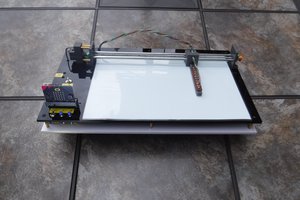

 leumasyerrp
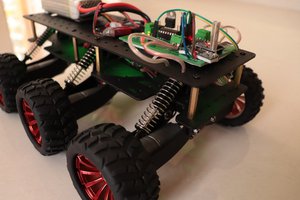
 Jithin Sanal