I'm still in the proof of concept stage of the project. This mostly means reading A LOT of documentation on all components and figuring if they will play nice together.
Next up is an IMU. I would like to learn how to integrate different positioning data and play around with mapping.
The sensors on the Roomba should give me direction and distance measurements from the distance encoders on both wheels. It would be nice to complement this with another and independent source of data.
I have a MPU6050 board laying around. This is a small 3 axis accelerometer and gyroscope giving 6 degrees of freedom.
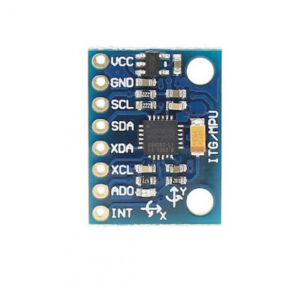
It operates on 3.3V, communicates using i2C and has an onboard DMP (Digital Motion Processor).
To utilize the full power of this device the DMP is the key. This way, I can offload some of the math to this external processor.
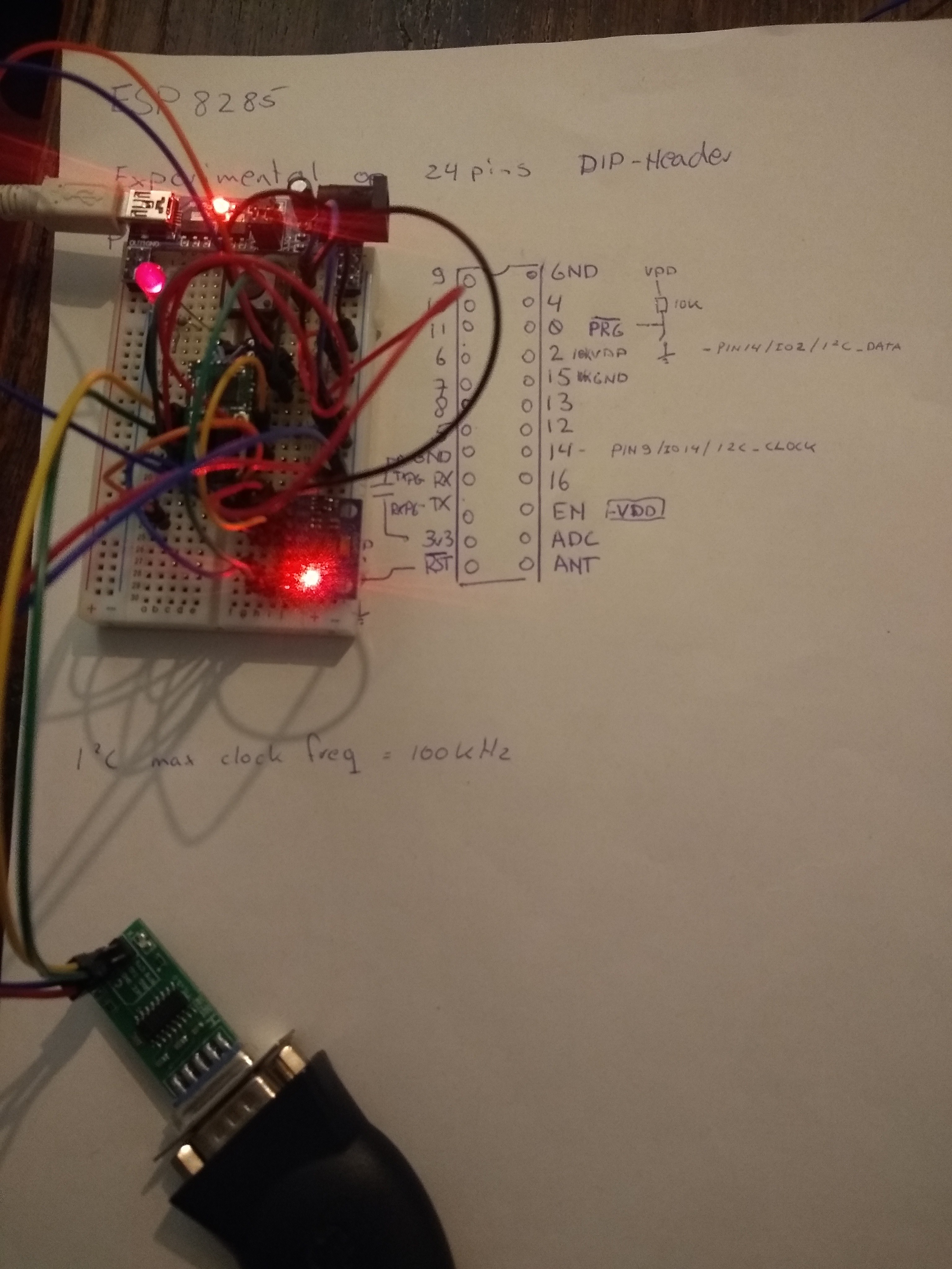
Time to get the prototyping sweater on. First up, connections:
The ESP8266 datasheet says the i2C pins are pin9/GPIO14 for i2C_CLOCK and pin14/GPIO02 for i2C_DATA. (Table 4-4. page 14-15)
This is a potential problem because GPIO02 is pulled up with a 10K resistor for the proper boot up mode. Further reading the datasheet of the MPU6050 and reading up on the i2C protocol tell me the clock and data lines should be pulled up typically with 4.7K resistors anyway.
I first tried with 5k resistors and this worked. So then I tried with the 10K in place with the GPIO02 and this also seemed to work. This is good news because I should be able to just connect it to what I already have soldered and I don't have to replace the resistor.
GPIO14 is still freely available, so this will get a pullup resistor and that should be it.
The ADD pin on the MPU6050 allows to set the LSB of the address. So the address on the i2C bus can be 0x68 on low or 0x69 on high. I will connect it to GND on the board.
Lastly there is the possibility to use the interrupt pin. It will flag when the DMP has it's results ready so a ISR can get the values over the i2C bus. Because the interrupt is on the rising edge (according to the i2C MPU library), this can piggyback on the pulldown on GPIO15 on the ESP8266.
I then checked this setup using a i2C address scanner sketch I found here:
https://diyi0t.com/i2c-tutorial-for-arduino-and-esp8266/
#include "Wire.h"
#define SDA_PIN 2
#define SCL_PIN 14
const int16_t I2C_MASTER = 0x42;

void setup(){
  Serial.begin(115200);
  while(!Serial){} // Waiting for serial connection

  Serial.println();
  Serial.println("Start I2C scanner ...");
  Serial.print("\r\n");
  byte count = 0;

  Wire.begin(SDA_PIN, SCL_PIN, I2C_MASTER);        // join i2c bus (address optional for master)
  for (byte i = 8; i < 120; i++)
  {
    Wire.beginTransmission(i);
    if (Wire.endTransmission() == 0)
      {
      Serial.print("Found I2C Device: ");
      Serial.print(" (0x");
      Serial.print(i, HEX);
      Serial.println(")");
      count++;
      delay(1);
      }
  }
  Serial.print("\r\n");
  Serial.println("Finish I2C scanner");
  Serial.print("Found ");
  Serial.print(count, HEX);
  Serial.println(" Device(s).");
}

void loop() {}
This tells me a device is found on address 0x68. Normal boot up and programming via UART also still work, so we're in business.
I'm not sure if the Wire library uses the correct pins though and any on chip hardware or if it just does some bit bashing. If I don't specify the pins, the example sketch doesn't work. This leads me to think the hardware pins aren't configured in the board info for the Arduino IDE.
Next up is a sketch to get raw sensor data. For this I used the library from here:
https://github.com/jrowberg/i2cdevlib
I only had to change the pins being used for i2C by adding
#define SDA_PIN 2
#define SCL_PIN 14
const int16_t I2C_MASTER = 0x42;
And change the Wire.begin(); to
Wire.begin(SDA_PIN, SCL_PIN, I2C_MASTER);This gives me readings, so now it's time for the DMP sketch. For this to work I had to change a few more things. First of all the interrupt pin is GPIO15 and I also added a LED to GPIO9 (why not)
#define INTERRUPT_PIN 15  // use pin 15 on ESP8266 (has 10K pulldown for programming via UART)
#define LED_PIN 9 // (Arduino is 13, Teensy is 11, Teensy++ is 6)
And the max speed for i2C on the ESP8266 is 100kHz according to the datasheet. So:
Wire.setClock(100000); // 100kHz I2C clock.
This would compile, but the ESP8266 crashed hard and the bootup message on the serial port would say something like:
20:08:22.373 -> load 0x4010f000, len 1384, room 16
20:08:22.373 -> tail 8
20:08:22.373 -> chksum 0x2d
20:08:22.373 -> csum 0x2d
20:08:22.373 -> v8b899c12
20:08:22.373 -> ~ld
20:08:22.431 -> ISR not in IRAM!
Ok. google to the rescue. Apparently, the ISR (Interrupt Service Routine) has to be placed in a special place in memory: IRAM. To tell the IDE this, you need to add "ICACHE_RAM_ATTR " when declaring the ISR function like so:
void ICACHE_RAM_ATTR dmpDataReady() {
    mpuInterrupt = true;
}
And now it worked. I'm getting messages with calibrated and integrated results!
The real test was when trying to combine this sketch with the rest of the code, but it worked. Together with WiFi, OTA updates, MQTT pub-sub, Roomba commands and retrieving sensor data.
I can notice it's becoming unstable though. There is an error now when I upload the sketch OTA:
Uploading.................................................................................................................................................................
18:15:40 [ERROR]: No Result!
18:15:40 [ERROR]: No Result!
And when I change something seemingly simple, it sometimes blows up, crashes and spews out nonsense or keeps rebooting. But it still works and proves all elements CAN work together.
Time to clean up the code, get it stable and add the MPU6050 to the "production" hardware together with the Buck step down DC/DC converter in stead of the LM7833.
Discussions
Become a Hackaday.io Member
Create an account to leave a comment. Already have an account? Log In.