I'm getting confident that my plans could actually work. Software is getting there. I'm getting inputs/sensor readings without delays so the ESP8266 can do some real processing soon. I love it when a plan comes together!
Time to sort out the power situation and add the IMU-hardware.
When I opened up the roomba I could see the LM7833 was indeed getting quite hot. The packing I added so everything was snug had actually melted/deformed a bit. The board also had some discoloration.
I still have plenty of space to change out the LM7833 with the Buck DC/DC step down power converter. This is the one I'm using: https://www.tinytronics.nl/shop/nl/power/spanningsconverters/buck-(step-down)-converters/dc-dc-step-down-buck-converter-1.5a-3.3v-output
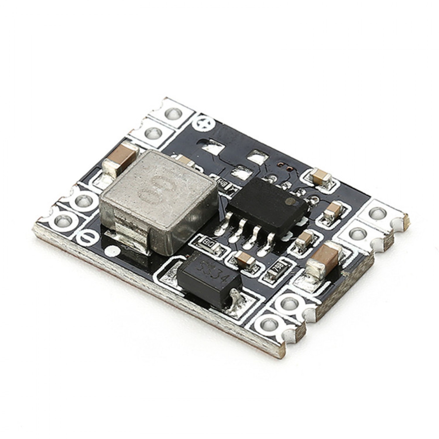
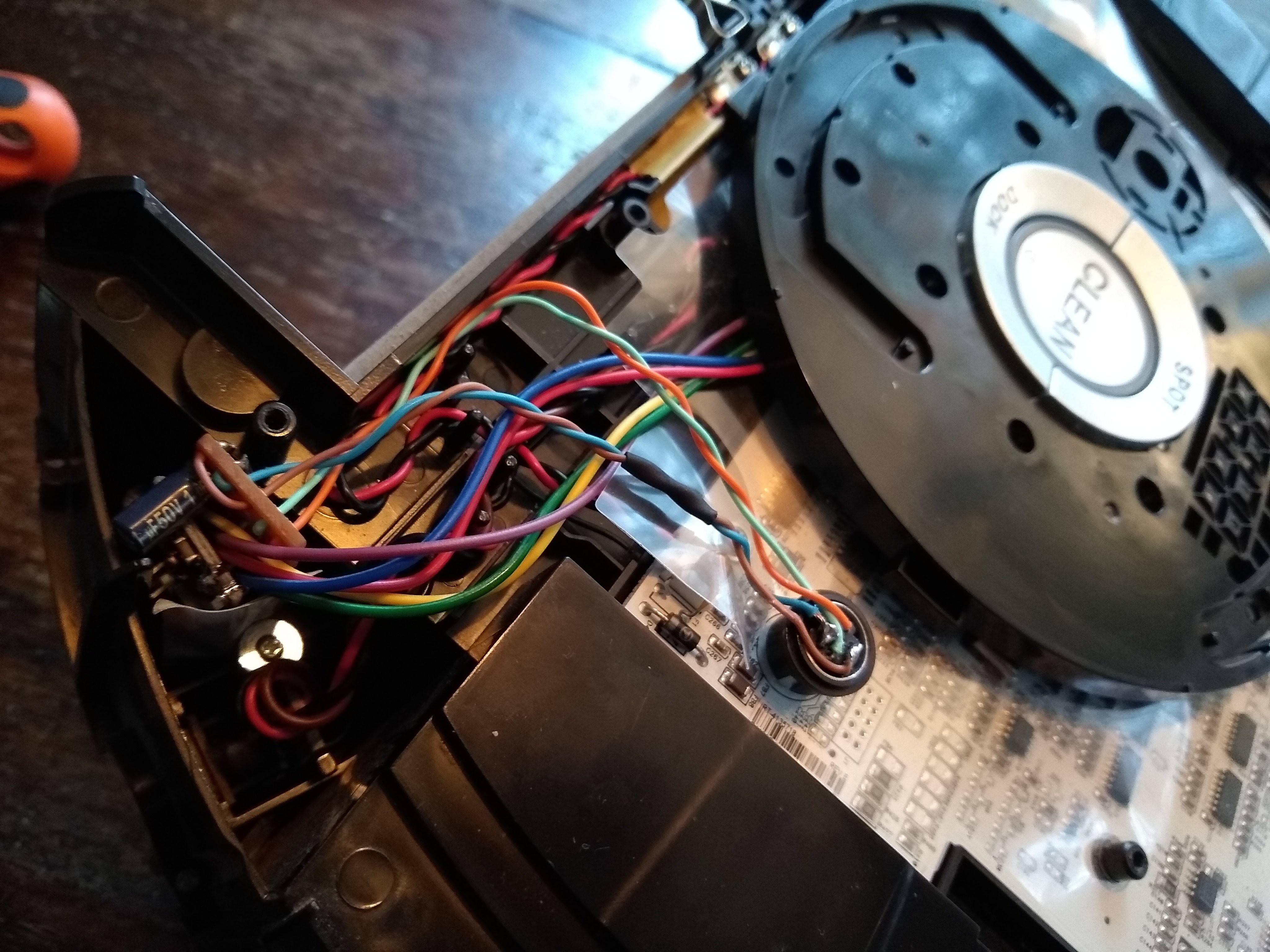
Desolder the LM7833, some rearranging with the wires, connect the GND's together and it all fits.
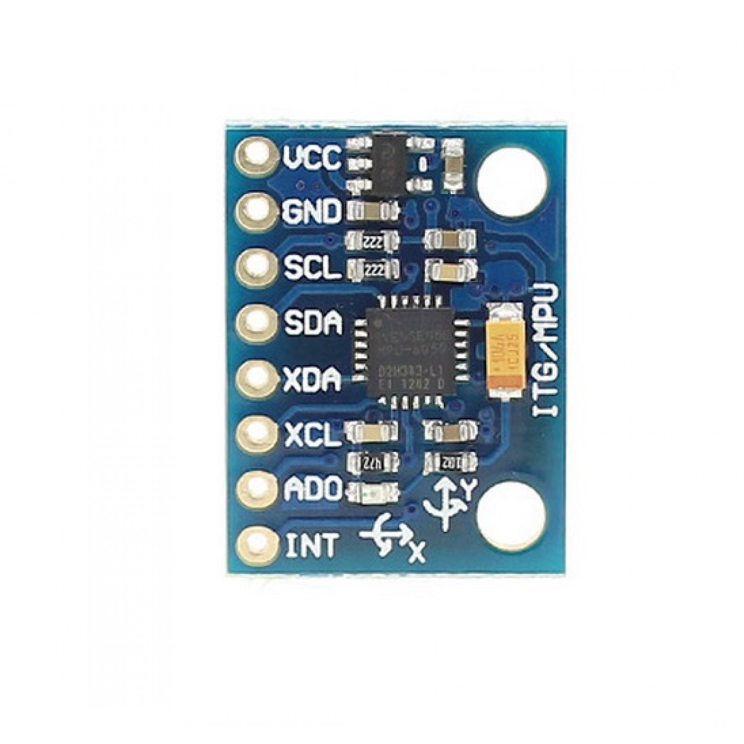
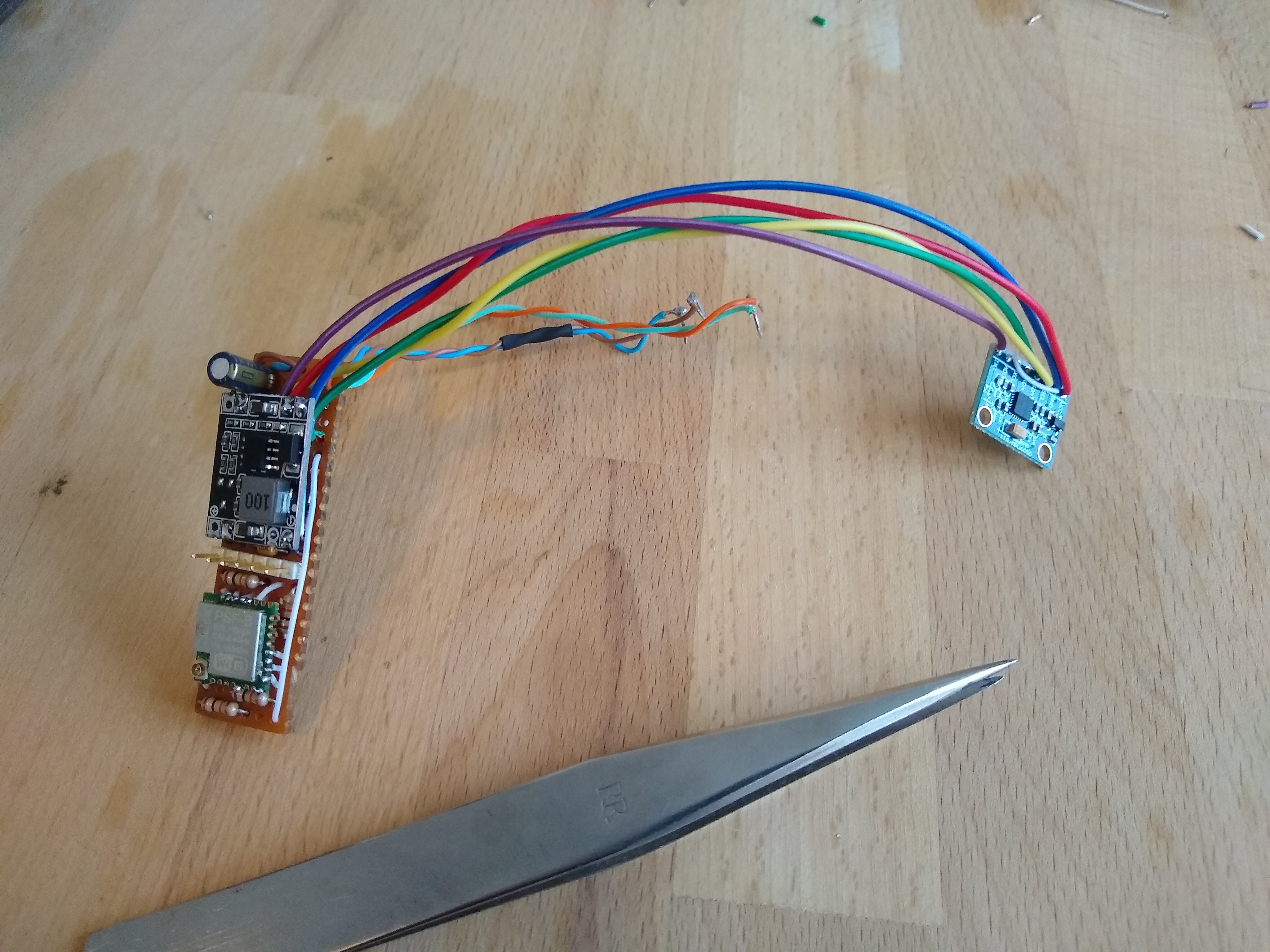
For the IMU, I'm using this:
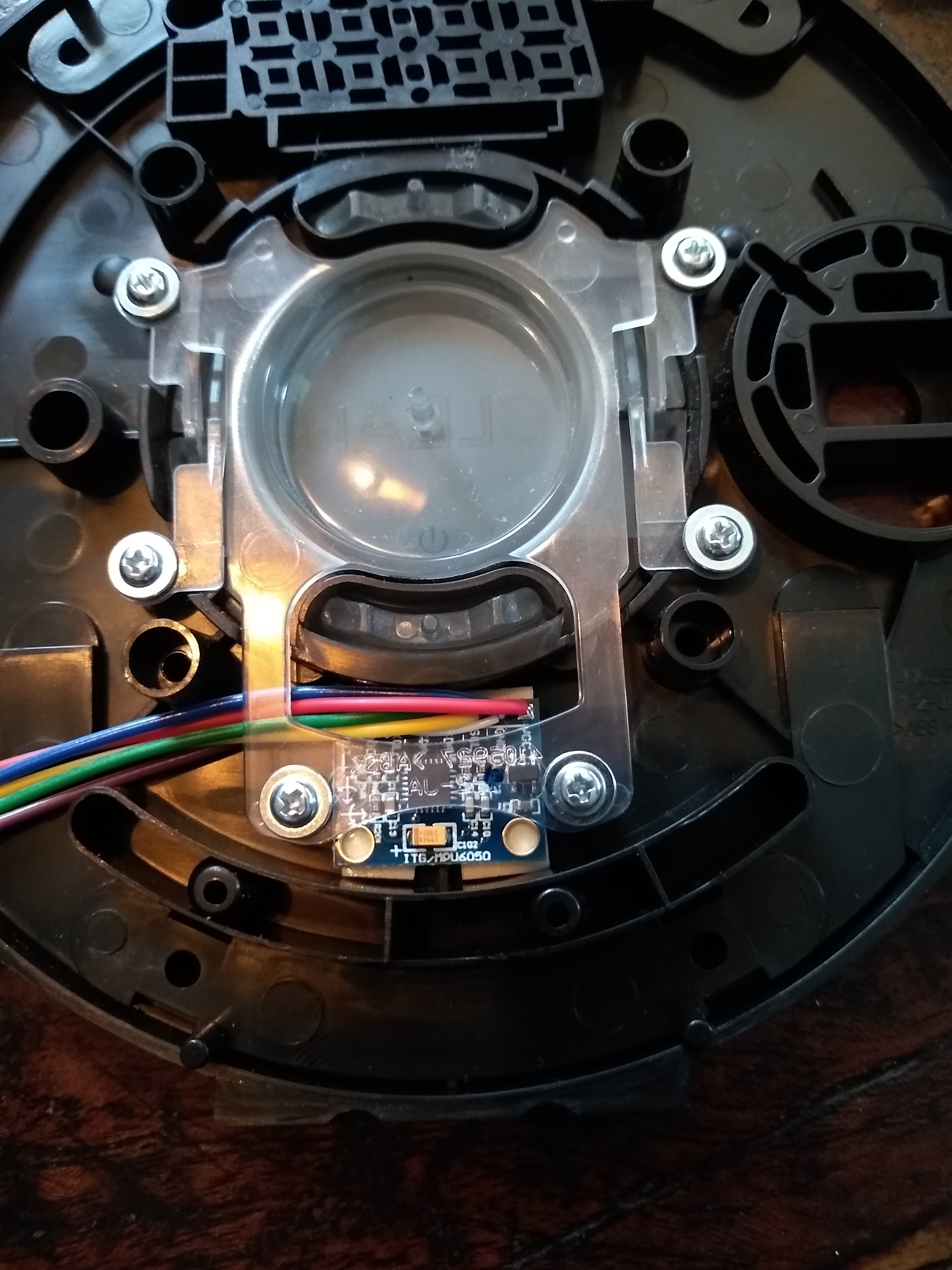
I want the IMU as close to the center of rotation as possible. This is in the middle between the wheels and turns out to be the location of the "clean" button. I will pace it just trailing the center when driving. I think this will give me the least problems when calculation position / track. Approximate location:
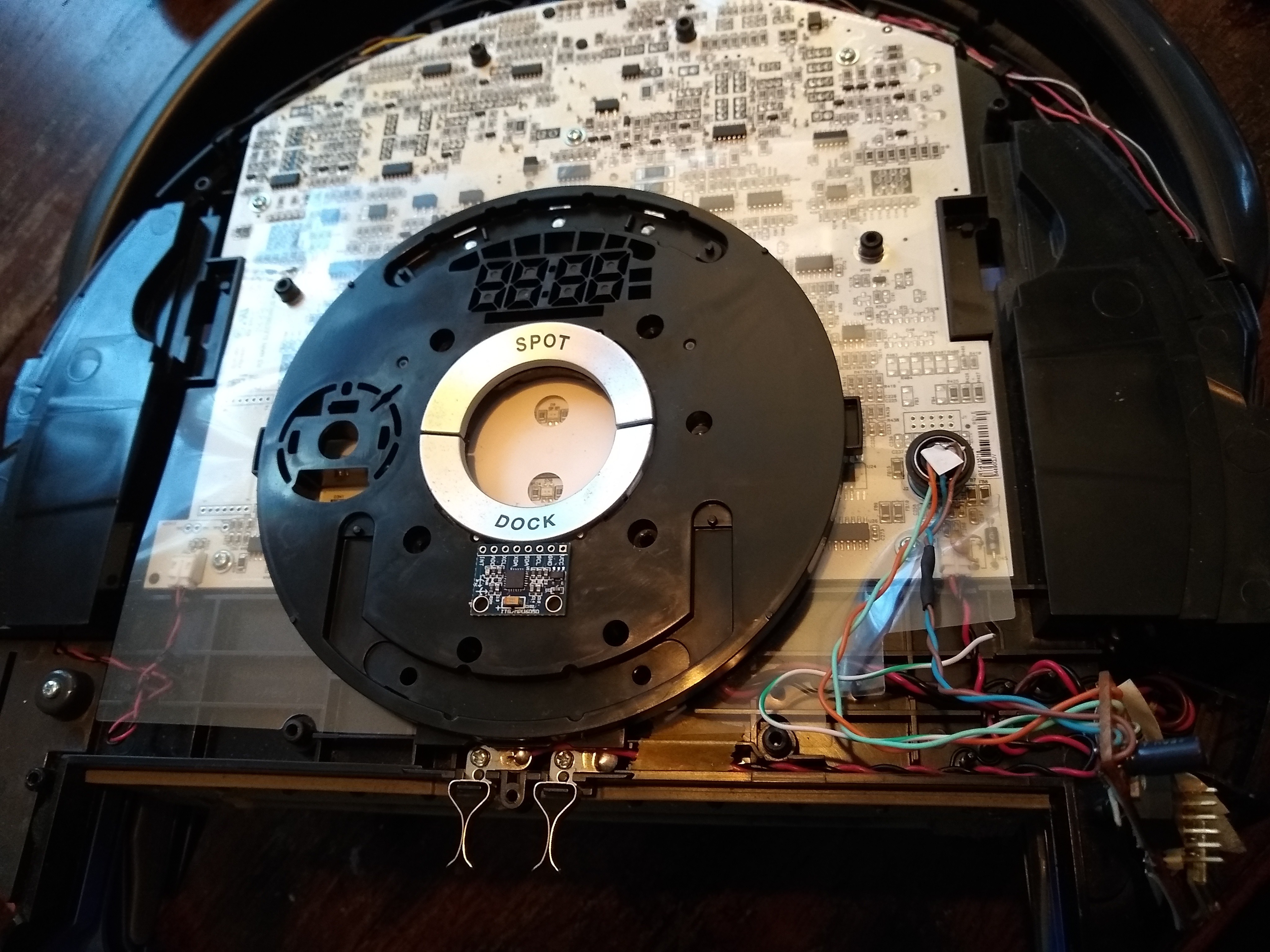
The panel for the buttons has some room underneath where I can also run the required wires.
For the MPU6050, I need 5 connections:
VDD, GND, I2C-Clock, I2C-Data, Data ready interrupt. The address pin is connected directly to GND on the board.
The clock gets a 5k pull-up to VDD and is connected to GPIO14 of the ESP8266;
Data needs a pull-up to VDD. I connect this to GPIO02 of the ESP8266 which already has a 10k pull-up to set the boot mode;
Interrupt needs a pull-down to GND (interrupt is on rising edge). So I connected this to GPIO15 which already has a 10k pull-down to set the boot mode;
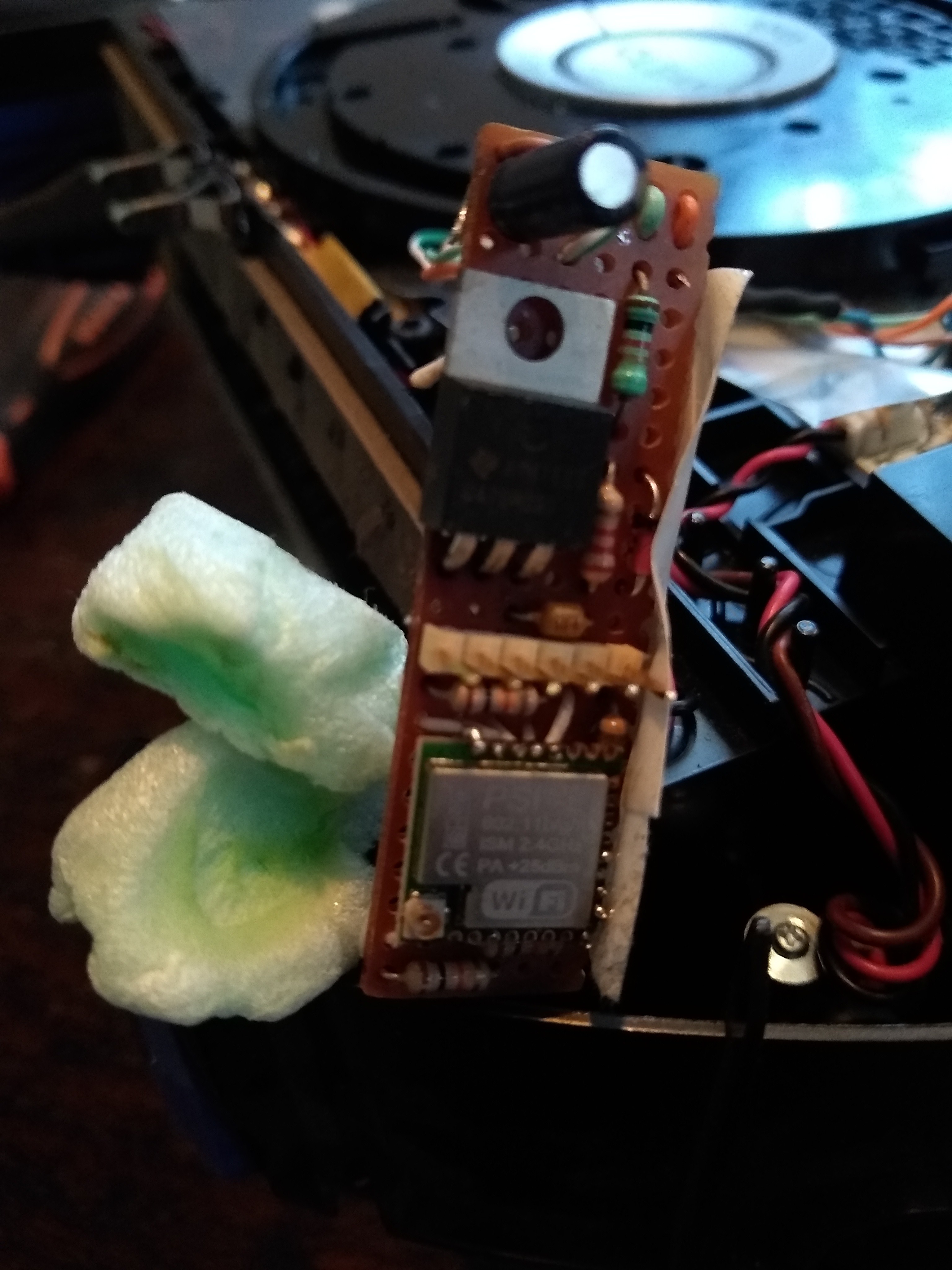
IMU and Buck converter all connected:
The IMU is fixed in place with some double sided foam tape. Neat!:
And everything in it's place, hopefully never to be seen again:
Closing everything up. Crossing fingers, safety glasses on and place the battery...
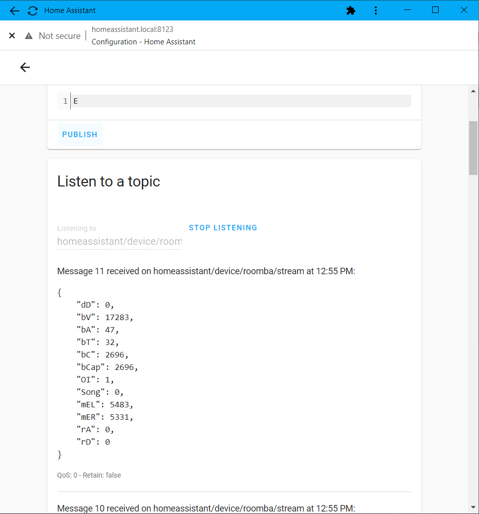
We're stil up and running! I have it set up so that it publishes it's internal values every 5 seconds when I enable the datastream.
The datastream will also continue 24/7 and is not interrupted by cleaning or other button presses.
So the ESP8266 get's the motor encoder data 66 times a second and IMU-data (from the DMP) 100 times a second?
It's getting exciting now!
Discussions
Become a Hackaday.io Member
Create an account to leave a comment. Already have an account? Log In.