I've incorporated the software to use the IMU into the main sketch. In a previous log I already figured out how to use it and what to adjust:
In previous attempts to use the MPU6050 everything got unstable. The main loop would only get about 400 runs/second. That's way too little for a usable system with stable communication.
The roomba's datastream puts out 66 messages a second. Each message containing approximately 50 bytes for a set of sensorpackets. We evaluate 1 serial byte every loop. So we need at least 3.500 loops a second to interpret the datastream.
The GitHub repository has some clues: https://github.com/jrowberg/i2cdevlib/issues/657
This seems like a weird decision to me, but okay. And when I use the interrupt flag as intended, I get about 10.000 loops a second!
void IMUHandler() {
  if (!dmpReady) return;
  // read a packet from FIFO
  if (mpuInterrupt) {
    mpuInterrupt = false; //Clear interrupt flag
    if (mpu.dmpGetCurrentFIFOPacket(fifoBuffer)) { // Get the Latest packet
      // display Yaw Pitch Roll in degrees
      mpu.dmpGetQuaternion(&q, fifoBuffer);
      mpu.dmpGetGravity(&gravity, &q);
      mpu.dmpGetYawPitchRoll(ypr, &q, &gravity);
      mpu.dmpGetQuaternion(&q, fifoBuffer);
      mpu.dmpGetAccel(&aa, fifoBuffer);
      mpu.dmpGetGravity(&gravity, &q);
      mpu.dmpGetLinearAccel(&aaReal, &aa, &gravity);
      roomba.AuxYaw = ypr[0];
    }
  }
}
Solved!
I then made arrangements so the positioning code can use the IMU-data. Along with some more tweaks for ease of use. I added "on the fly" calibration of the IMU and output of the offset-values over MQTT. Now I can hardcode the starting offsets in the sketch.
I noticed the ESP8266 will crash hard when trying to calibrate with wrong starting values or in a different orientation. It will crash a first time, but the MPU6050 will have received different offsets. A reset and therefore a second pass at the calibration routine works. And the offsets we get over MQTT can be uploaded in the next firmware and all is well.
The result of a full cleaning session, position calculation with the IMU for orientation and encoders for distance. Logging 5 times a second cleaning for ~20mins. Green arrow = starting position, Red dots = finish and docking. Those two should line up:
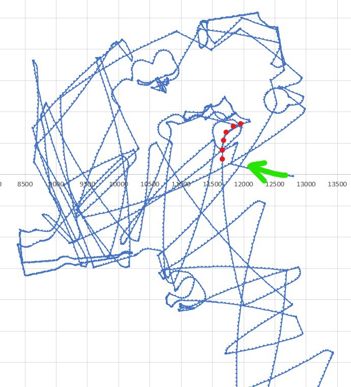
This is clearly better than before. I can kinda figure out where my table and chairs are. But when I did a full cleaning session of an hour:

Question now is... is this better?? Most important is that any source of the large error is not stochastic, but systemic and therefore correctable. After that we can solve the minor stochastic errors.
And we have everything in place to tweak the system and I'm confident we can get there.
So now we've got:
- Stable software with Over The Air updates;
- Stable power and WiFi connection;
- Roomba encoder and sensordata every 15ms;
- Properly callibrated and fused IMU-data every 10ms;
- (async) MQTT interfacing;
- Ways to calculate real time positioning;
- Ability to do scripting;
I will upload the Arduino sketch I have so far.
Discussions
Become a Hackaday.io Member
Create an account to leave a comment. Already have an account? Log In.