0%
0%
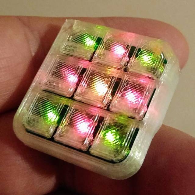
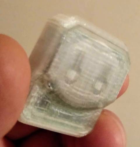
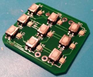
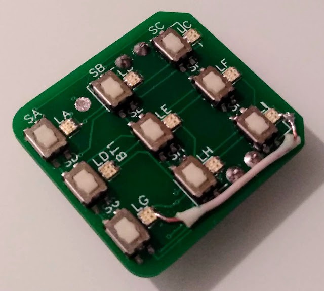
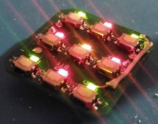
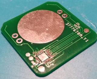
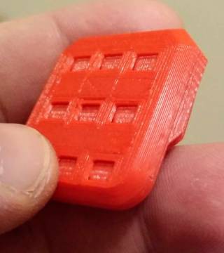
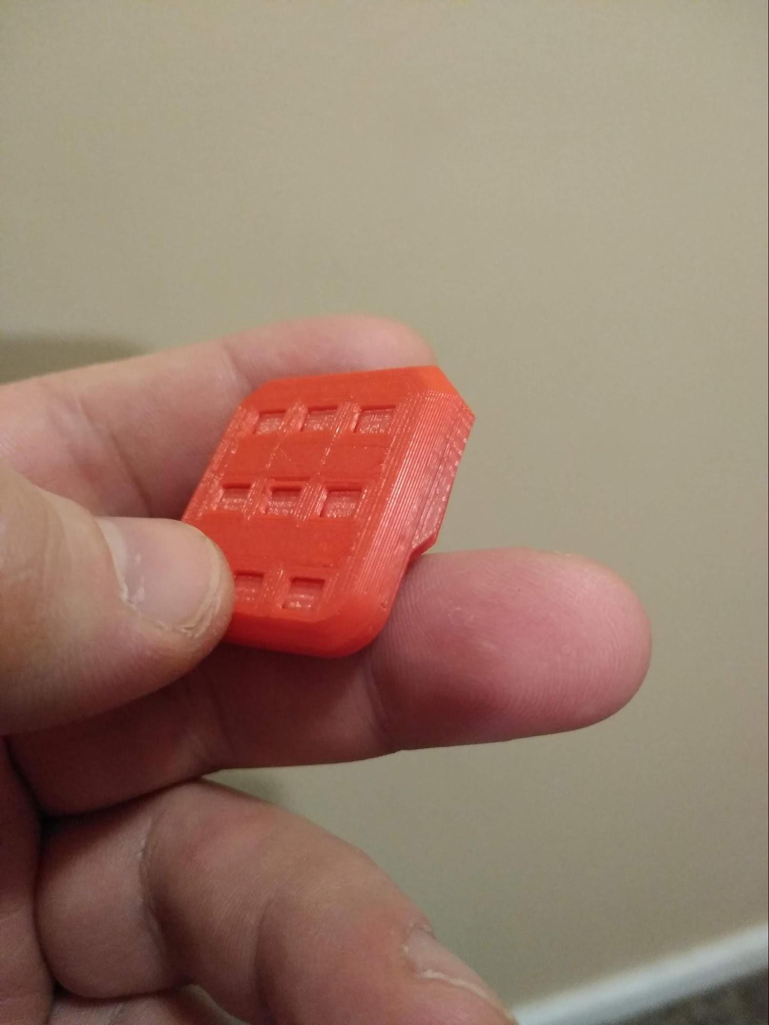
Alien Die
a pocket fidget cube, puzzle, board game aide, and messenger
 Andrey Kalmatskiy
Become a Hackaday.io member
Already have an account? Log in.
Just one more thing
To make the experience fit your profile, pick a username and tell us what interests you.
Pick an awesome username
hackaday.io/
Your profile's URL: hackaday.io/username. Max 25 alphanumeric characters.
Pick a few interests
Projects that share your interests
People that share your interests


 Jeremias
 vishal soni
 Erik Bosman
 C. Scott Ananian
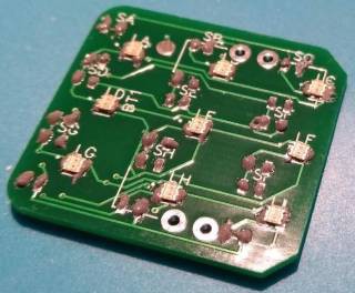
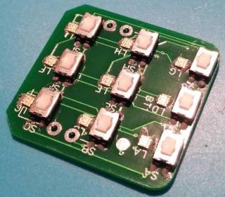
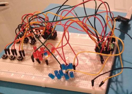
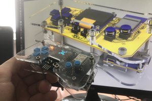
Hey! Oh, that's an interesting project! Got any pictures of the side with buttons looks like when soldered?