0%
0%
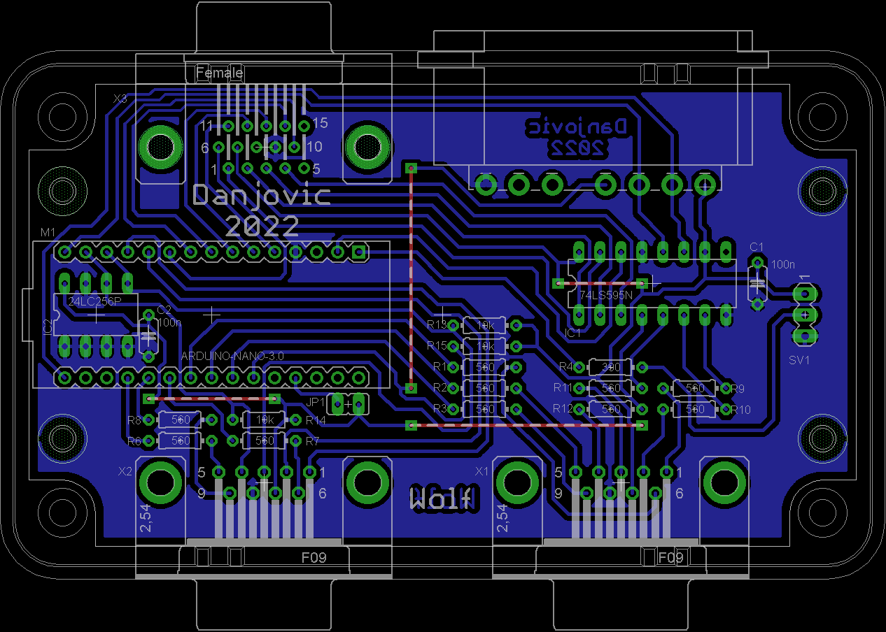
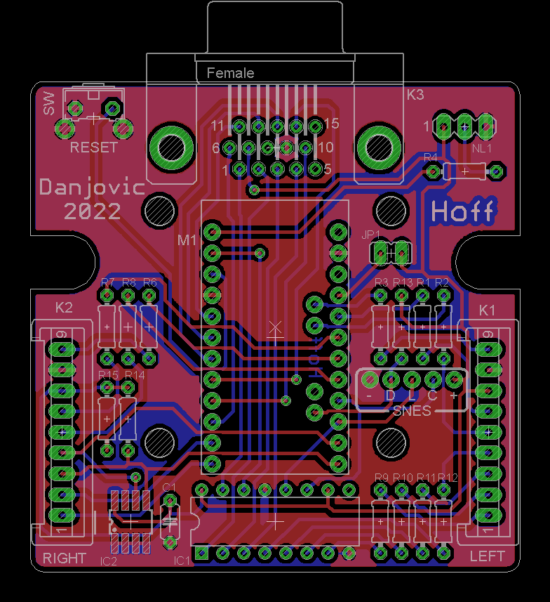
Wolf
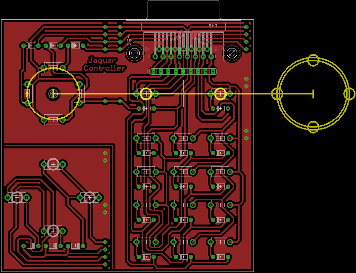
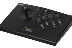
Use a Jaguar or SNES controller as a joystick and a keypad in Atari 2600 and 7800
 danjovic
Become a Hackaday.io member
Already have an account? Log in.
Just one more thing
To make the experience fit your profile, pick a username and tell us what interests you.
Pick an awesome username
hackaday.io/
Your profile's URL: hackaday.io/username. Max 25 alphanumeric characters.
Pick a few interests
Projects that share your interests
People that share your interests
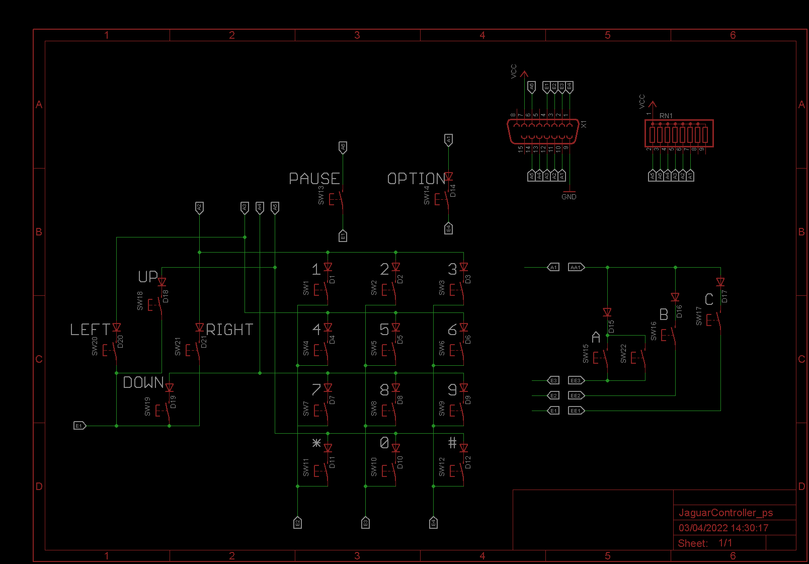
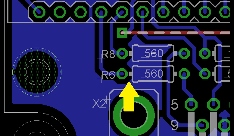
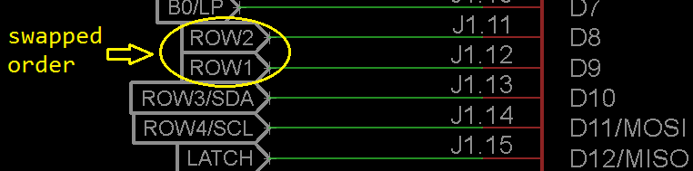 This one was fixed by software, just swapping the constants on the switch() inside the interrupt routine.
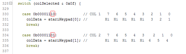
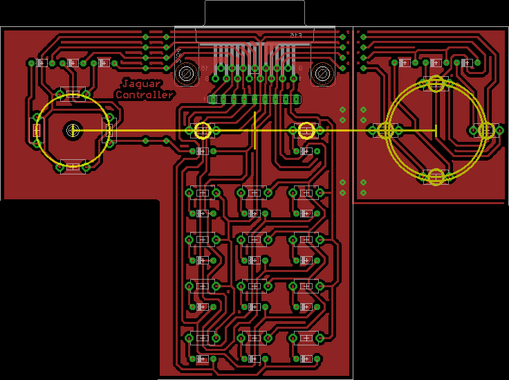
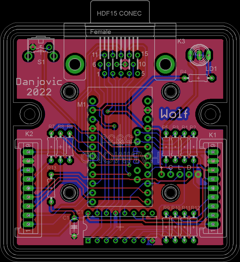
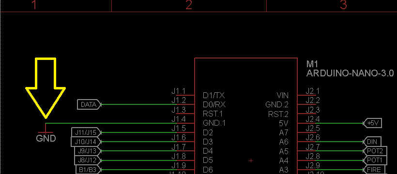 It was already fixed and the updated schematics and PCB were submitted to GitHub
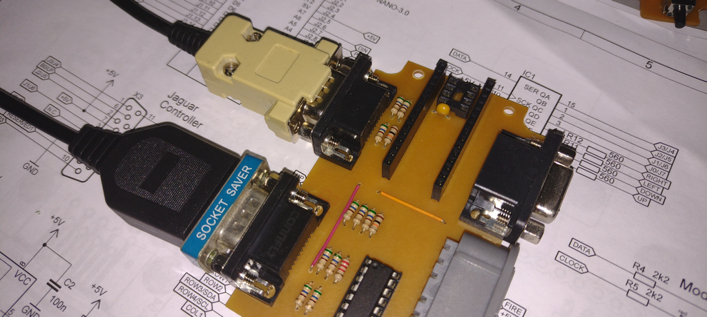


 Oleg Utkin
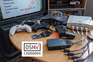
 Jacques Gagnon
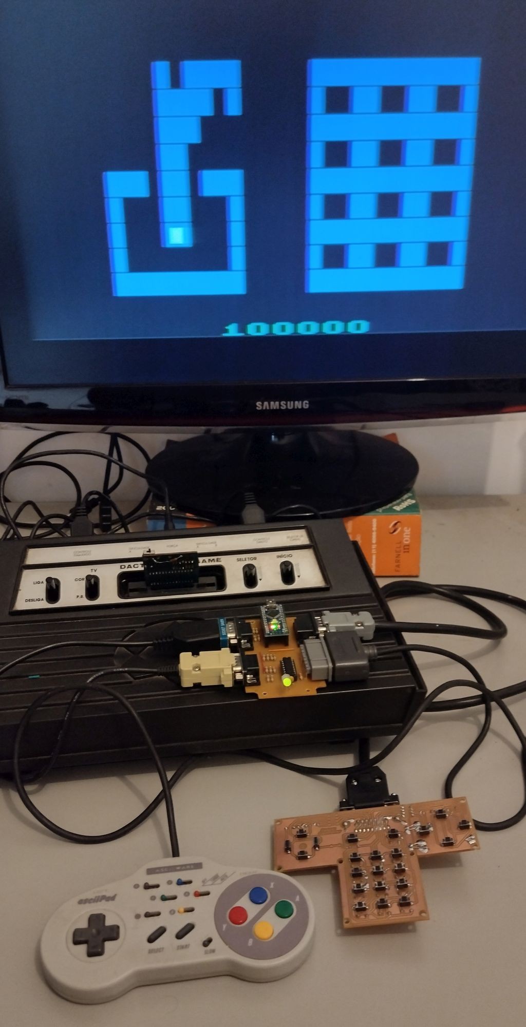
Now that the 2600+ is on the horizon with new 7800 games and peripherals, it would be an excellent time to get the Wolf adaptor out to developers and gamers.
Many ATARI fans will love the Wolf adaptor, as its already compatible with *every* 2600 and 7800 game.
It will allow for game-specfic keypad overlays to be included with new 2600/7800 games.
The keypad will be great for rpgs, simulators, strategy games, text/graphic adventures and ports of classic micro computer games to ATARI's 2600 and 7800 systems.