0%
0%
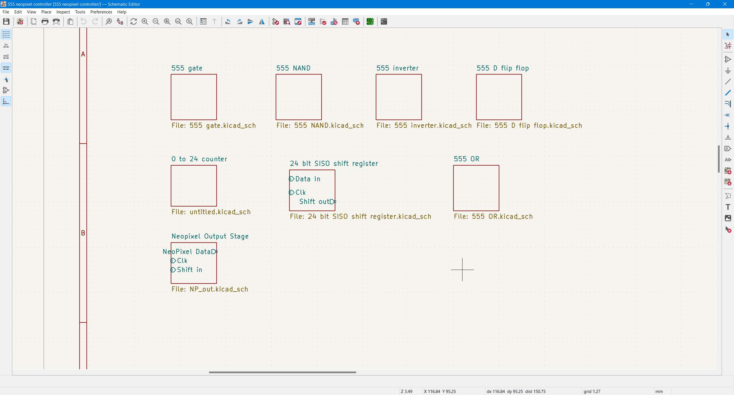
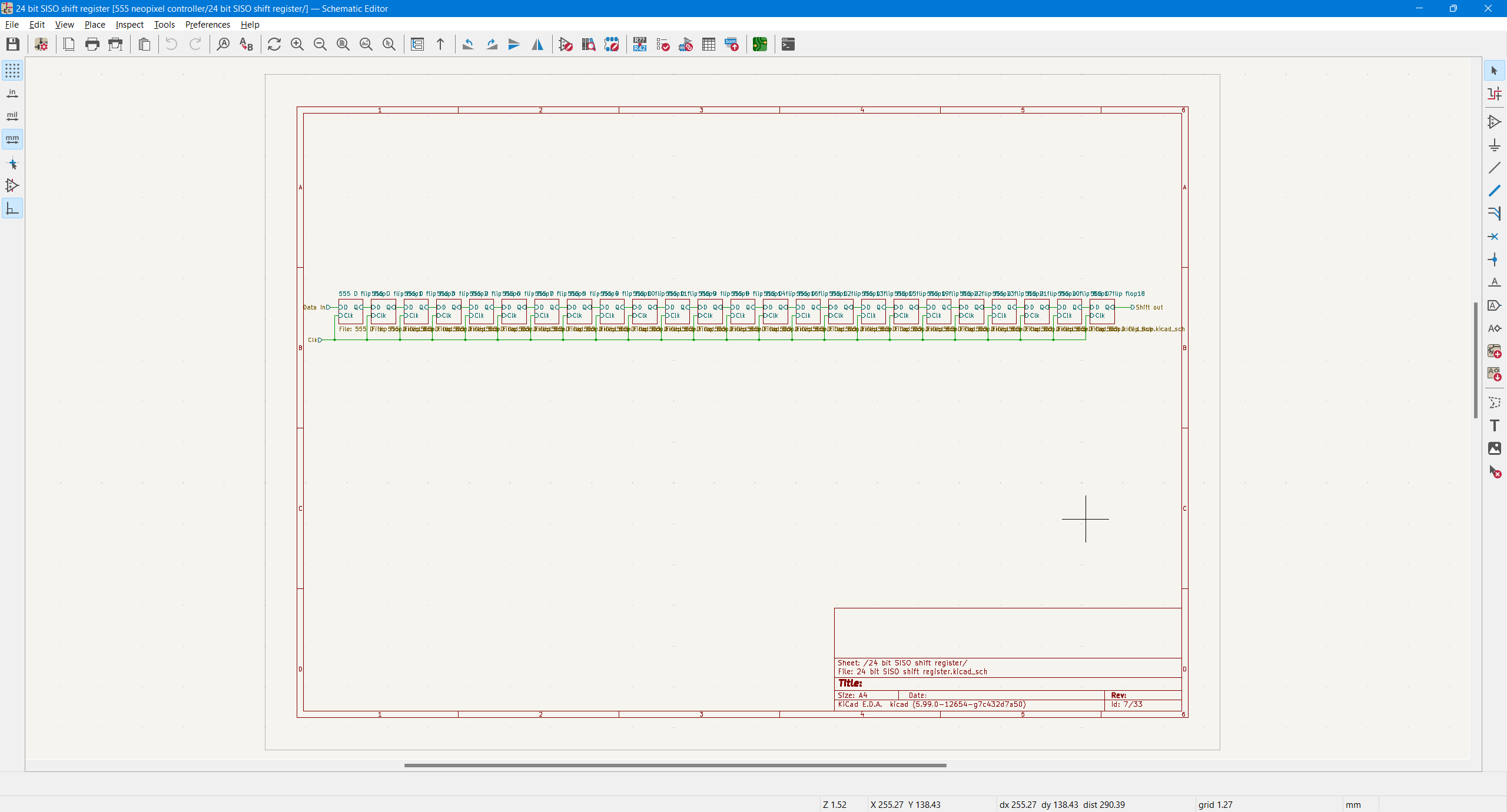
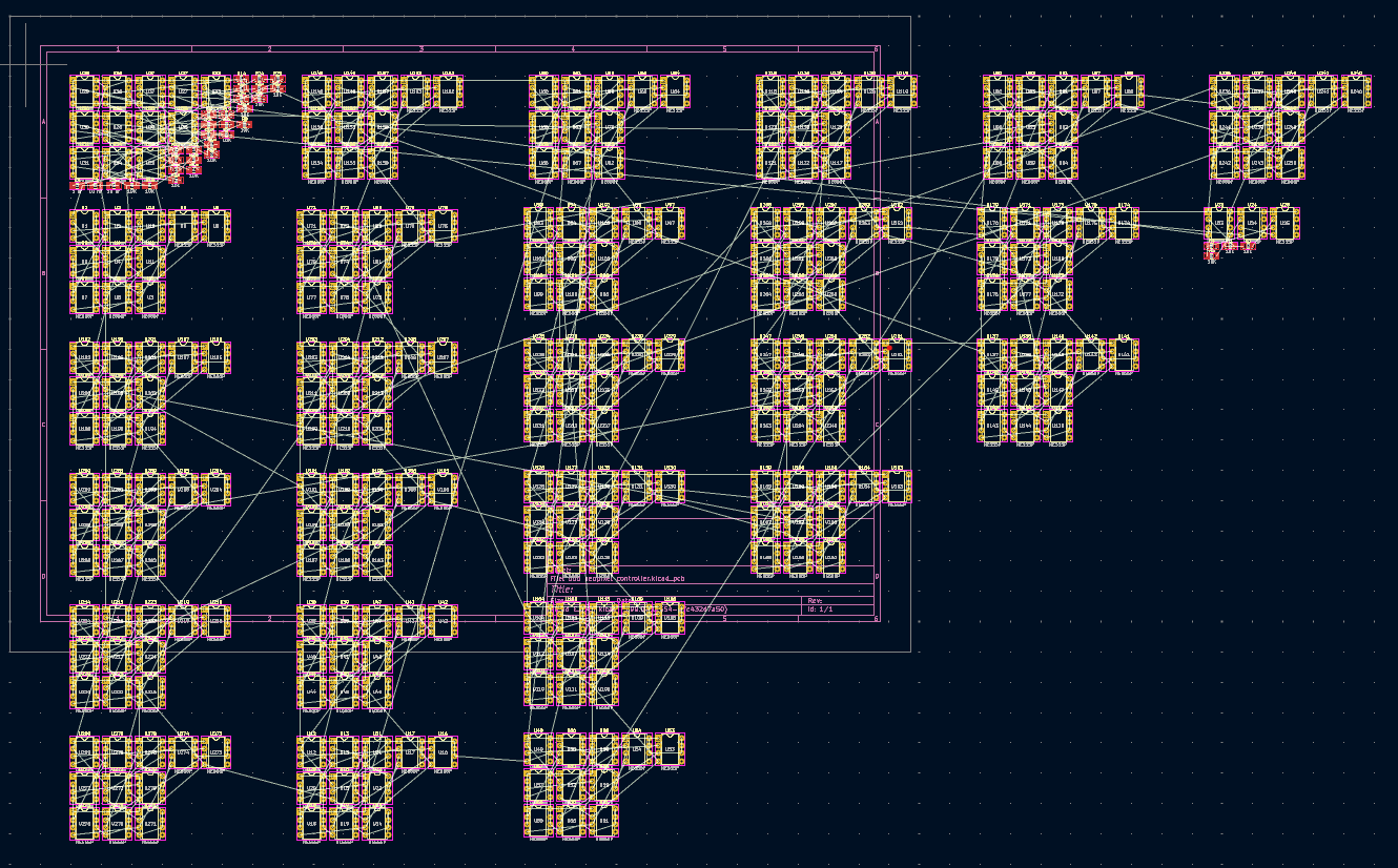
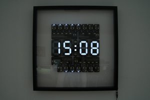
The Rube Goldberg 555 Neopixel Controller
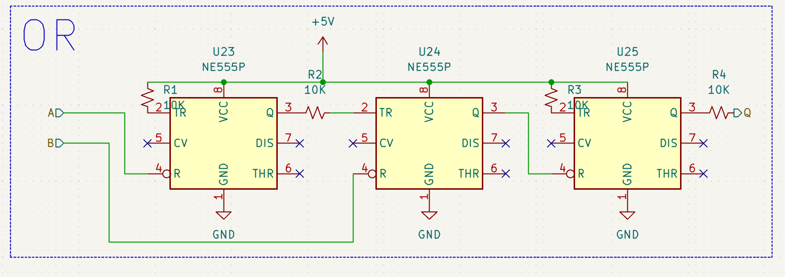
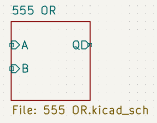
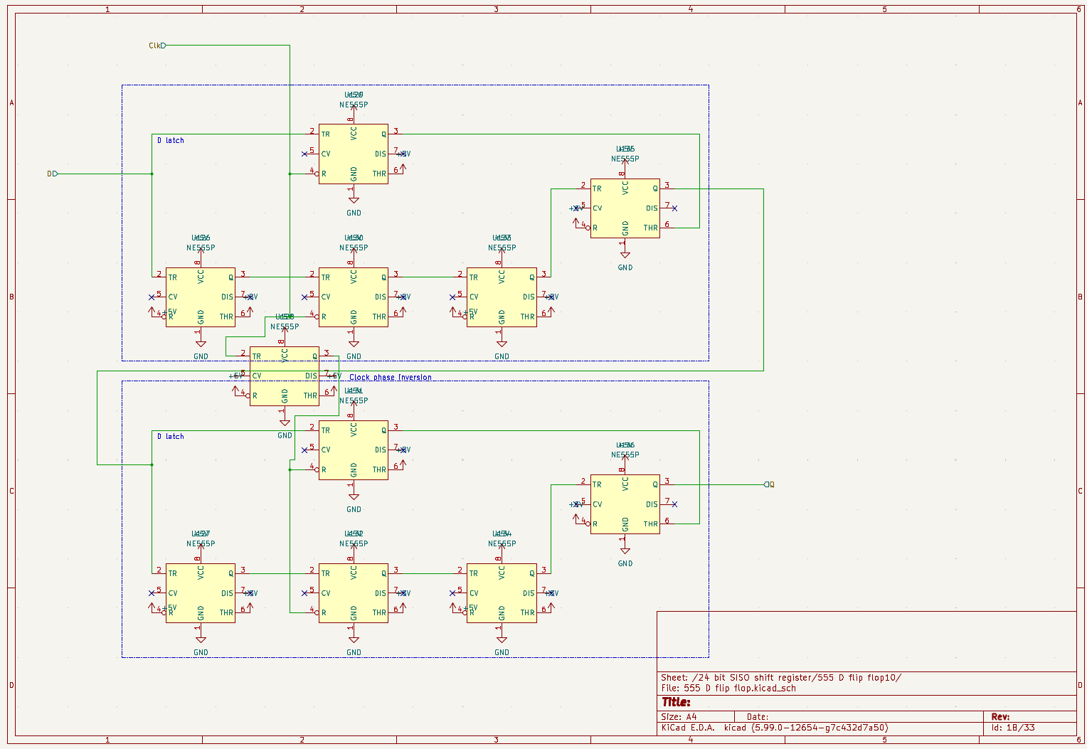
Manually control a single Neopixel with a toggle switch. 555 clock and data output, 555 shift register... 555 delay line memory??
 Paul
PaulBecome a Hackaday.io member
Already have an account? Log in.
Just one more thing
To make the experience fit your profile, pick a username and tell us what interests you.
Pick an awesome username
hackaday.io/
Your profile's URL: hackaday.io/username. Max 25 alphanumeric characters.
Pick a few interests
Projects that share your interests
People that share your interests
 SwiftyTheFox001
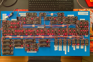
 Joël de Kanter
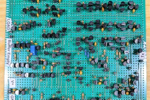
 Eric Ljungquist
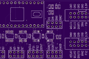
 Paul Stoffregen