This is actually 3 projects rolled into one.
1) There is the woodworking - saws, routers, 3018 CNC router, etc - required to make the box itself as well as the designs and LED windows on the lid.
2) There is the software required to get a Raspberry Pi Zero to run the phrase recognition software (PocketSphinx) and control the I2S microphone, LEDs and solenoids. This project didn't have room for a USB microphone; this I2S microphone from Adafruit
https://www.adafruit.com/product/3421
is tricky to set up but is super compact and works great.
3) There is the electronic circuitry required to keep the current in 'wait' mode as low as possible so the battery doesn't go dead while the box is sitting on a shelf.
The power management part gave me the most trouble. The box may sit around for weeks or even months but still has to have enough juice in the battery (3.7V 18650 Li ion) to run the Pi, the LEDs and the solenoids (1 A apiece). The Pi Zero I/O bus pulls current even when the CPU is shut down, as does the LED bar, so the power to these components needs to be completely disabled in wait mode.
In the end, the device that saved this project was this Pololu switch:
https://www.pololu.com/product/2808
It is switched on and stays on when it receives a momentary positive voltage at the ON terminal. It's output is high enough to run the Pi board and the LED bar but not the solenoids, so I configured one of the Pi I/O pins to trigger an N-channel MOSFET which drives the solenoids. On shutdown, the Pi Zero sends a signal (using gpio_shutdown) to the Pololu OFF terminal and the switch cuts power to the Pi Zero and the LED bar.
The only significant power draw in wait mode for this project is one of the momentary capacitive touch sensors (Adafruit AT42QT1010). The wait current for the Pololu switch is ridiculously low, and is negligible compared to the capacitive switch. I cut the trace and moved the blob on the capacitive switch that reduces the duty cycle and my cheapo ammeter tells me it now pulls about .3 mA, which is gonna hafta be good enough. There are actually two of these switches in this project, purely for aesthetics. One switch gets V+ from the battery and draws a steady current (the .3 mA). When you touch this switch its output goes to the second capacitive switch, so it is now "hot." Touching the second switch while it is hot sends a signal to the Pololu switch which then powers the Pi, which begins booting. The point is that you have to touch both of the copper designs on the lid at the same time to wake the device.
If you look at the lid you see a pair of copper circles close to the anvil designs. If you put 3.7V across them then the solenoids will open even if the internal battery is dead.
You may have noticed that the Pi Zero is not getting a full 5V - the 3.7 V from the battery is connected to the 5V rail.
This isn't exactly recommended procedure and I popped a few boards in the prototype phase, but the final version includes a P-channel MOSFET in a reverse voltage protection circuit and there hasn't been a problem since.
/----------/ Software
I have been assured that running a USB microphone would have been much easier, but there simply wasn't enough room for one. Adafruit's I2S microphone is wonderfully compact but has to be hardwired to the Pi Zero in a very specific way. Adafruit has a good set of docs for RPi
https://learn.adafruit.com/adafruit-i2s-mems-microphone-breakout/raspberry-pi-wiring-test
The volume in the recorded file is a bit low when you first get it running, but there is a recipe for adding volume control that works great, so the sensitivity can be cranked right up.
There are several voice recognition packages out there, but only one was suitable for this project. This is a standalone...
Read more »
 Guy Dupont
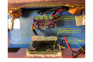
 Filip Mulier
 Craig Hissett
 KM4EFP