 padnest
A computer with no I/O capabilities doesn't do much... right?
So here we have the I/O board that will implement these interfaces:
- USB serial :: to communicate with a modern PC
- SPI (TTL) :: to experiment with any external SPI device like LCD display, sensors, real time clock, etc
- SD card :: the mass memory to read and write files
- GPIO user port :: for whatever else we want to connect
- P/S2 keyboard :: the primary input device
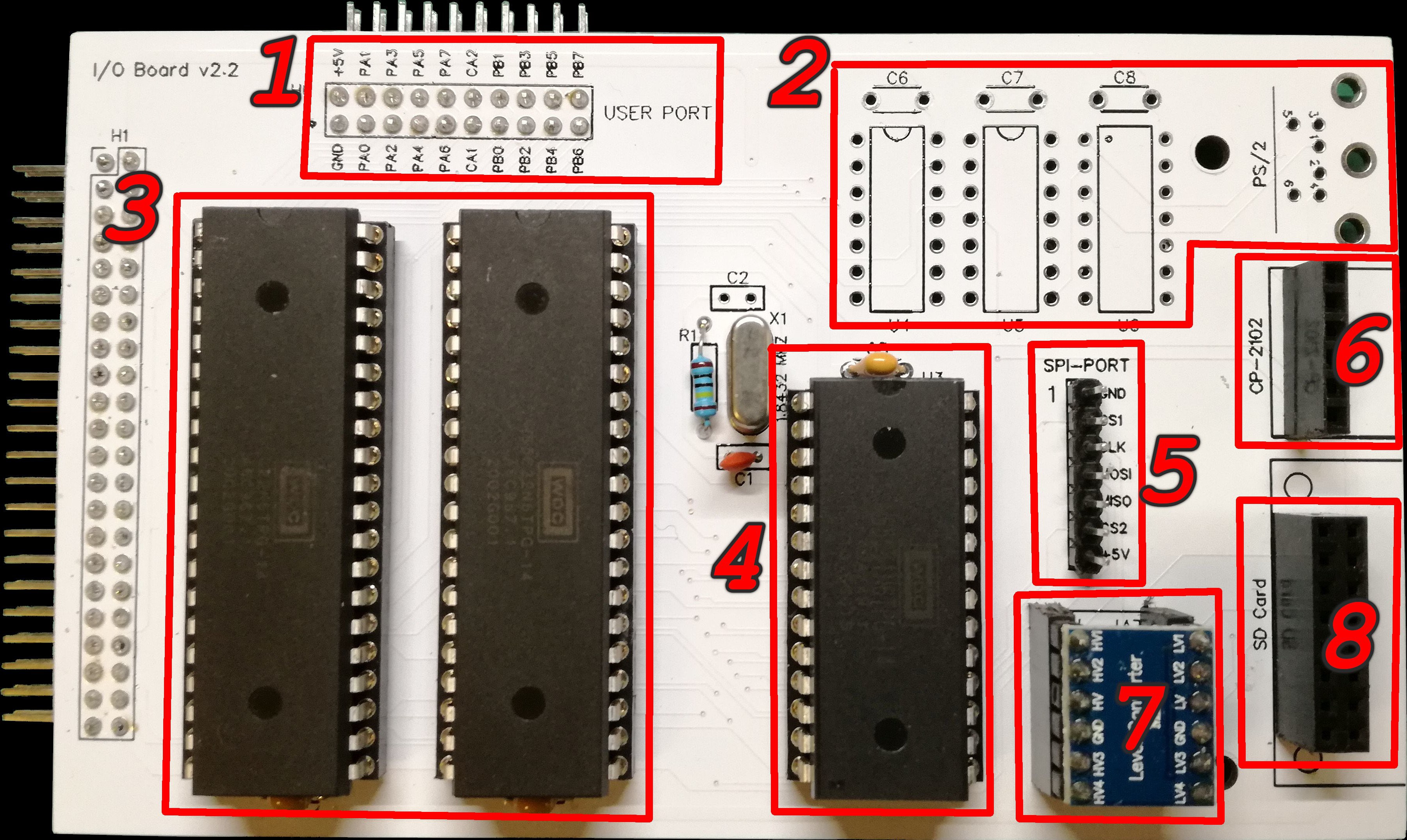
The I/O board has:
- User Port header for GPIO (1)
- PS2 keyboard adapter (2)
- two VIA W65C22N-14 for parallel and SPI comm (3)
- one ACIA W65C51N-14 for serial comm (4)
- SPI port header supporting two general TTL devices (5)
- CP-2102 module socket for USB serial (6)
- SD levels adapter module (7)
- SD card module socket (8)
Schematics: here
User port (1)
It is a GPIO port directly connected to the peripheral data ports of VIA#1.
This port also provides the system power supply (+5v).
PS/2 keyboard adapter (2)
Is the logic needed to adapt a standard PS/2 keyboard protocol to the VIA#2.
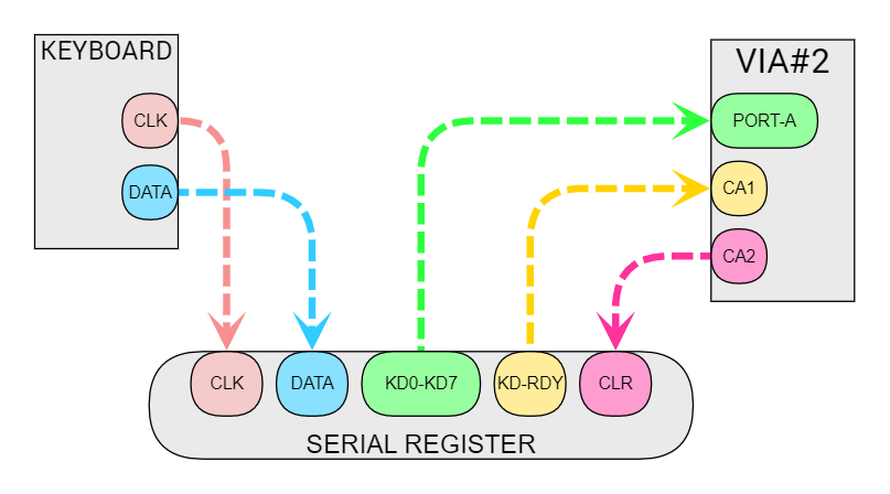
The PS/2 keyboard clock and data lines go into an external serial register (74LS164) that feeds VIA#2 with:
- KD0-KD7 ==> the keyboard data byte received (8 bits)
- KD-RDY ==> the keyboard data byte ready signal (when a complete data byte is received)
VIA#2 CA1 is configured as input to fire an CPU IRQ when keyboard data byte has been received and can be processed.
VIA#2 CA2 is configured as output to clean the serial register in order to receive the next keyboard data event.
Perhaps it will also be necessary to add a protection between the logic and the VIA#2 port.
VIAs (3)
Two WDC Versatile Interface Adapters W65C22N (datasheet) are connected to the system bus in this way:
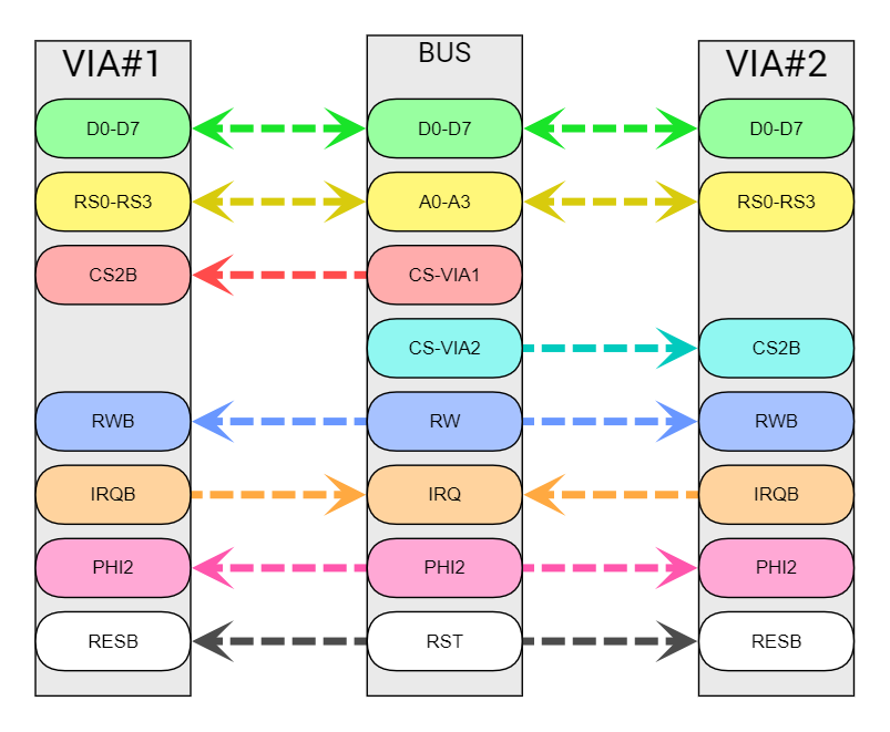
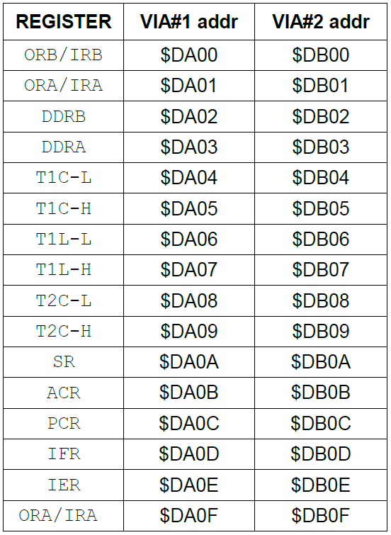
Each VIA has 15 internal registers that can be accessed by address llines A0-A3.
The base address is $DA00 for VIA#1 and $DB00 for VIA#2 and the memory mapping will be:
ACIA (4)
The WDC Asynchronous Communications Interface Adapter W65C51N (datasheet) is connected to the bus in the same way but it has only 4 internal registers so just two address lines, A0-A1, are used:
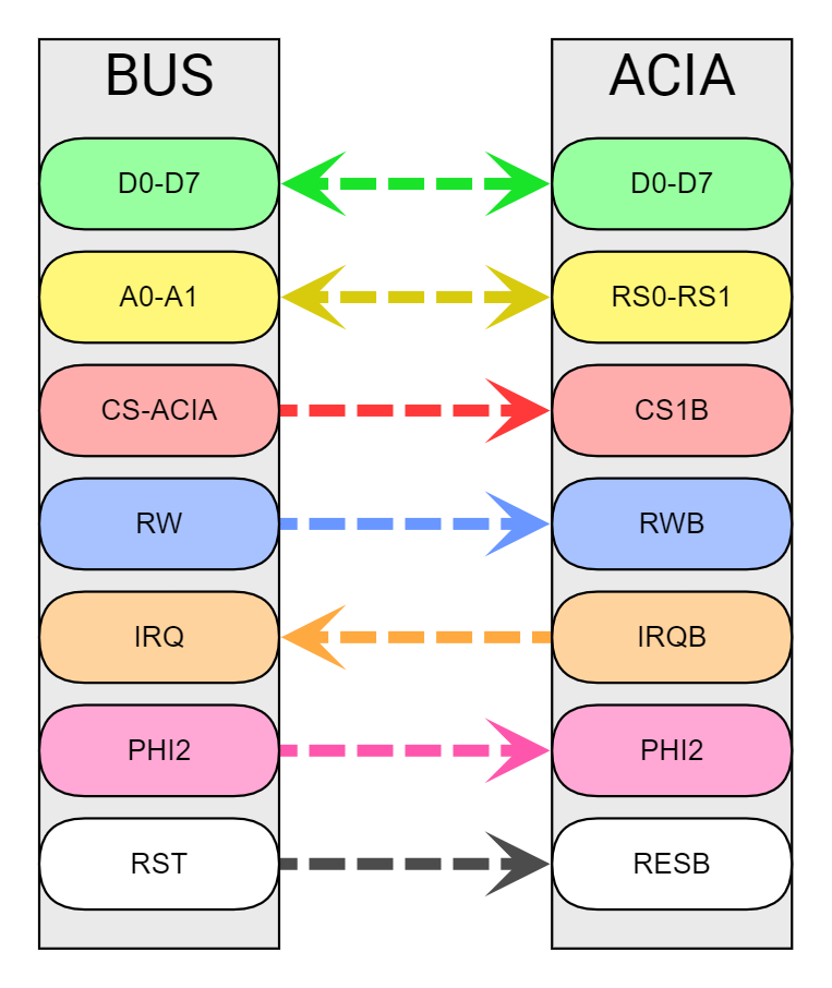
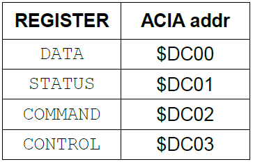
The ACIA base address is $DC00 and the memory mapping of internal registers will be:
SPI port and SD card module (5 & 8)
The SPI protocol is hardware implemented using the serial registers of the two VIAs: this allows us to have the maximum possible data transmission speed!
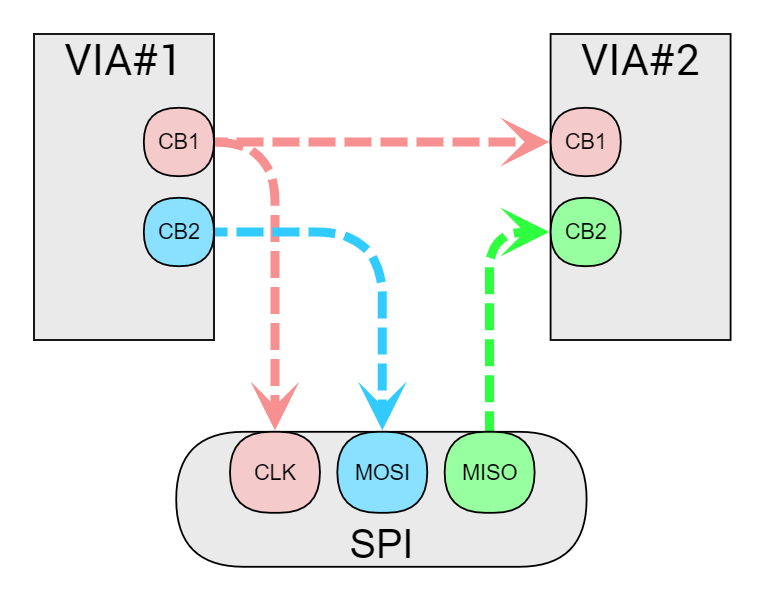
CB1 is configured as serial clock output on VIA#1 and as serial clock input on VIA#2.
CB2 is configured as serial data output (MOSI) on VIA#1 and as serial data input (MISO) on VIA#2.
Perhaps it will also be necessary to add a protection between VIA#1 CB1 and VIA#2 CB1.
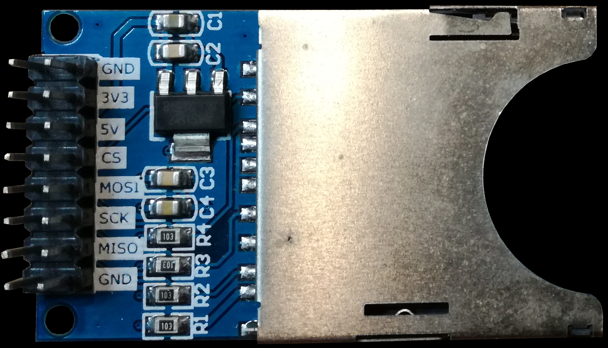
SPI is shared between the SPI Port and the SD Card module; the SPI port has two dedicated CS lines connected to VIA#2 PB5 and PB6
Here the popular Arduino SD Card module that I have choosen:
Usb serial (6)
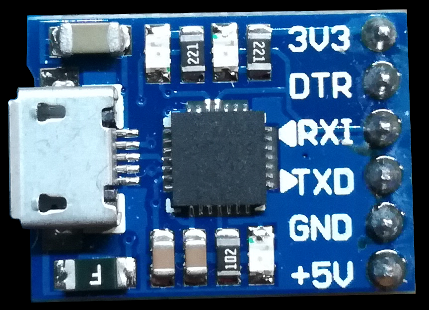
The usb serial interface is provided by a CP-2102 usb serial module and is connected to the ACIA:
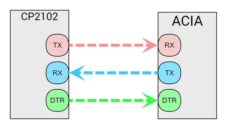
Here the CP-2102 usb serial module I'm using:
Stay tuned for the next step!
Ciao!
Discussions
Become a Hackaday.io Member
Create an account to leave a comment. Already have an account? Log In.