First posted to TekScopes at groups.io in several installments; here consolidated, with a few pictures added, and lightly edited.
Introduction
Put the kettle on. Here follows a long story about fixing a Tektronix 5A26 dual differential amplifier plugin, one of many different plugin modules for Tek's 5000-series oscilloscopes. Tek sold the 5xxx scopes from 1971 to 1991 and these plugins starting in 1976. Numbers that look like date codes suggest this unit was assembled in Q2 1980. They're kind of like old sewing machines: still useful and heartwarmingly fixable. If this sort of thing floats your boat, you might like #Tektronix 5D10 digitizer in 5441 (5440,5403) scope too.
NOTICE/spoiler: most of what follows turns out wrong in the end. If you got here by way of a search for information, maybe start at the end and read backwards!
Chapter One
This may be a unique fault and not directly useful for any future reference, but sometimes I enjoy reading how someone worked through a problem. Maybe someone will like to read this.
I bought a 5A26 dual differential amp "as is" from grainy photos that showed little except that it was not perfectly clean. So I get to take what I got and like it.
All the pushbuttons were terribly stiff or not functional at all. No big surprise and solved with solvents. Access to the bandwidth limit switches required some disassembly, which required some desoldering, but that much was well enough described in the manual and no big deal.
There were some glops of dried goop on the faceplate and a couple of the BNCs had more corrosion on them than I wanted to compact into whatever I might connect to them. Cleaning that up turned into a round of disassembly, cleaning, breaking, fixing, and things that could have been easier if I knew what I was doing. I might write more about some of that another day as a B-side to this.
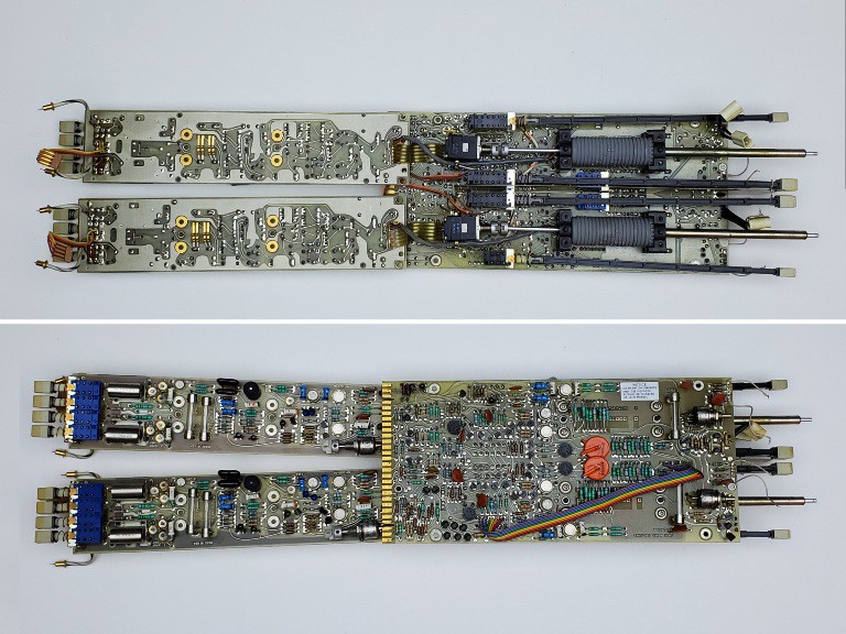
It worked pretty well, if not perfectly calibrated, in dual trace mode or when displaying channel 2 only.
The "interesting" part was that when displaying only channel 1 it showed two vertically separated but otherwise identical traces. At slower sweep rates, it was clear that the two copies of ch1 were generated by ALTernation or CHOPping as if the plugin was displaying both channels. Also the same when combined with one or two traces from another plugin: with the 5A26 set to display ch1 only and a second dual trace plugin installed, the scope cycled through two traces from the other plugin and two identical but offset copies of ch1, by alternation or chopping, as though it were cycling through four traces from two dual trace plugins. With the 5A26 in dual trace mode the scope cycled normally through four legit distinct traces. Channel 2 worked normally, either by itself or in dual mode with ch1.
Chapter Two
So the displayed voltage of channel 1 was shifting with trace alternation.
The rest of this will make more sense with reference to "output amplifiers <2>" schematic:
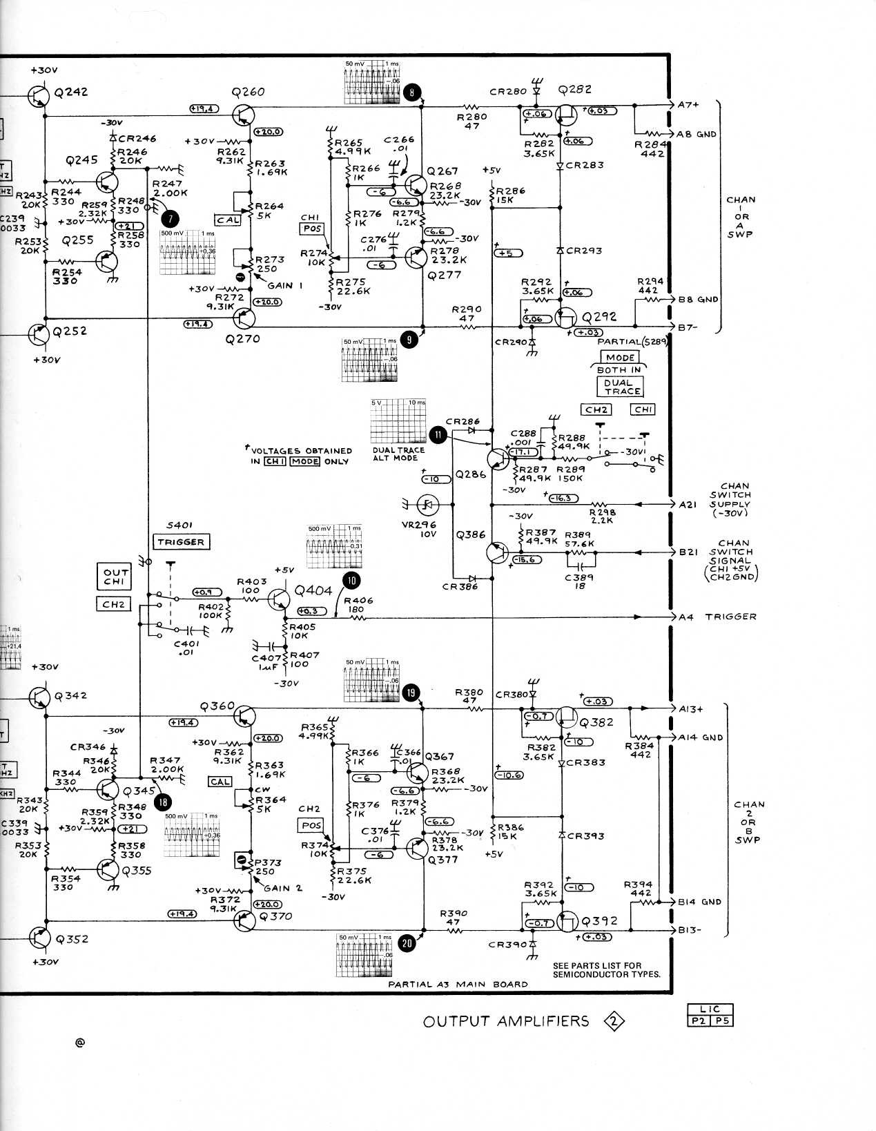
I don't have a plugin extender. Of course the output stuff is on the right side of the plugin, not accessible through the left side of the scope frame. So diagnosis continues by pulling out the plugin, clipping leads onto points of interest and replacing the plugin in the left slot with leads hanging out from the empty right slot. Repeat.
I set the ch1 inputs to GND and ran a sweep slow enough to see the alternation.
Of course output voltage between the drains of Q282/Q292 changed with alternating sweeps. The drain of Q282 was steady and Q292 alternated. So that narrowed it down a bit. The emitters of Q242 & Q252 were both steady 19.4V, as indicated on the schematic. The difference between collectors of Q260 & Q270 alternated with Q260 steady and Q270 alternating. Q242 & Q252 drive the bases of Q260 & Q270, so at Q270 the base is right and the collector is wrong.
FETs Q282/Q292 handle channel switching by...
 Paul McClay
 Dylan
Dylan
 jaromir.sukuba
 sky-guided
 Yann Guidon / YGDES