 Tim
TimThis is a simple approach how to emulate the behavior of the LEDs with a microcontroller.
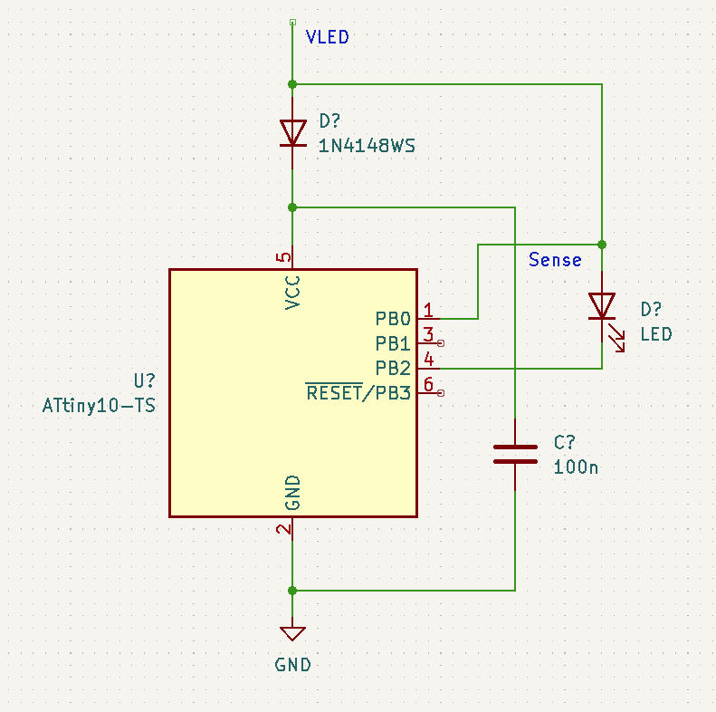
Data is sent by pulling VLED to GND for a few µs. While VLED is at GND, the diode is in revese direction and the remaining charge from the capacitor will power the microcontroller. The capacitor is recharged after VLED is pulled to positive voltage again.
The Sense input on PB0 can directly sense the signal from VLED. In case there are concerns because of V(PB)>VCC, another diode may be inserted. But the voltage differential is only ~0.6V, which should still be acceptable.
The LED is driven by PB2. When VLED is pulled to GND it will turn off. A resistor for current limiting should be added as well.
If you are very adventerous, you could also omit the diode. In that case, the MCU will be powered by the ESD diode on PB0, which should also charge the capacitor via the VCC pin.
Discussions
Become a Hackaday.io Member
Create an account to leave a comment. Already have an account? Log In.