 leadacid44
To recap, here are the steps as outlined by the instructions I found on the internet:
- Remove charger from vehicle, Remove 8 screws on top,
- Remove 3 bottom screws that secure the AC panel,
- Loosen the AC input panel and rotate 90 degrees to access the PC board,
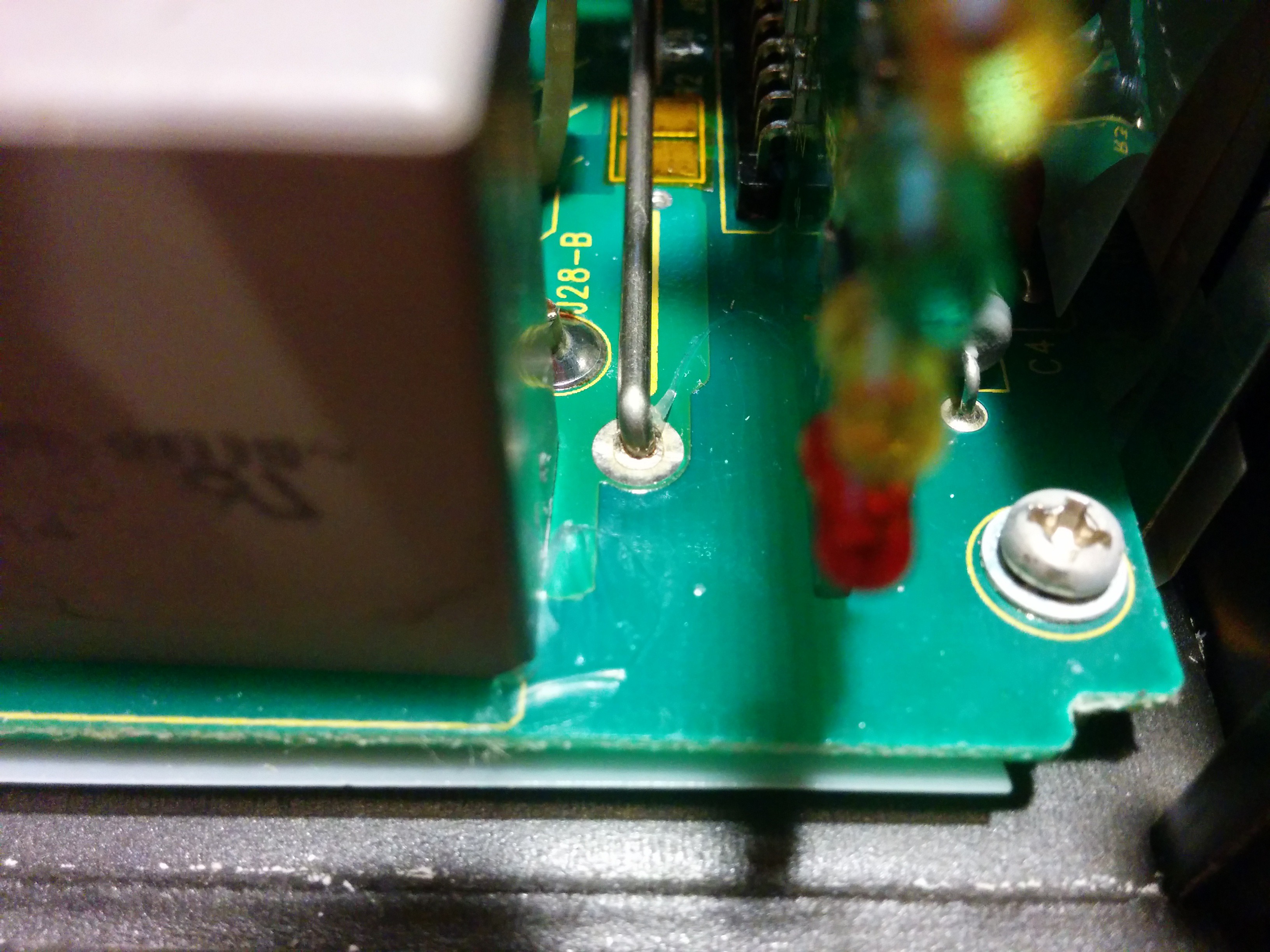
- Locate the current shunt wire located where the PC board meets the LED board,
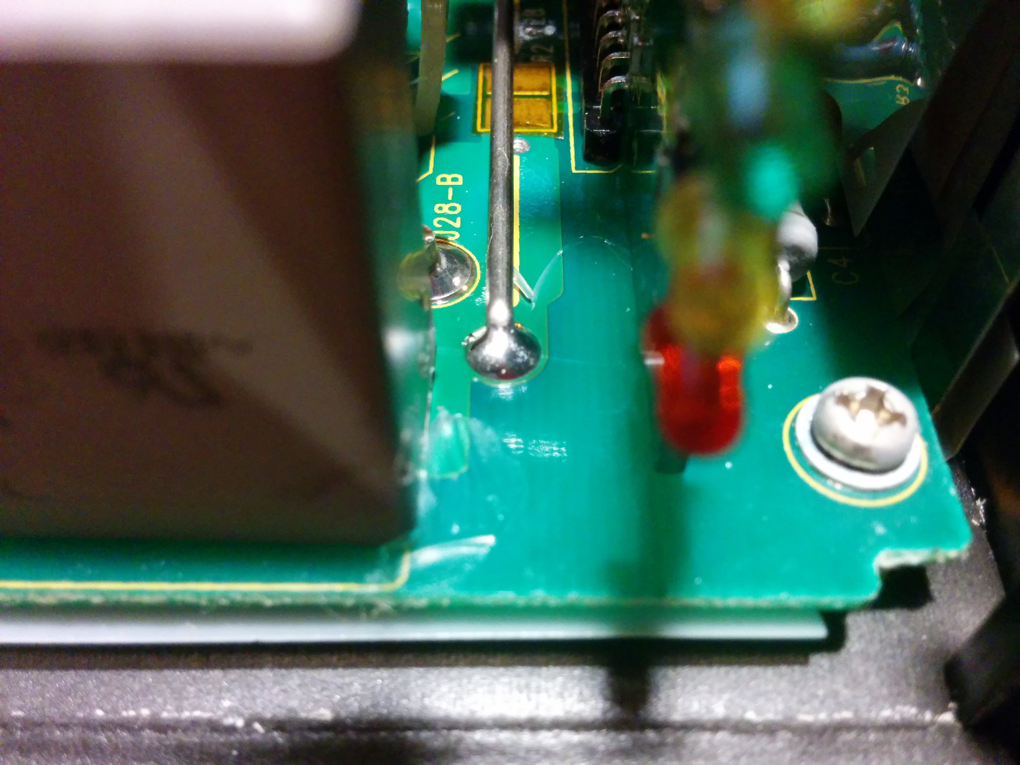
- There is a limited amount of solder on one end of the wire. Scrape the conformal coating until the wire is shiny and solder with 60/40 resin core,
- Reassemble by re-rotating the AC panel and install the bottom center screw until flush then complete the assembly.
Okay, sounds easy enough. First things first, removing the charger from the car. On my Zenn, this was a fairly straight-forward process. I would strongly recommend disconnecting the main battery pack and removing the front plastic on the car. Its about 4 bolts, four plastic clips (which will invariably break when you try to remove them) and the whole operation should swing away from the car by some pivots up by the lights. Unclip from the lights and you can remove it in one piece. You will see the QuiQ on the right.
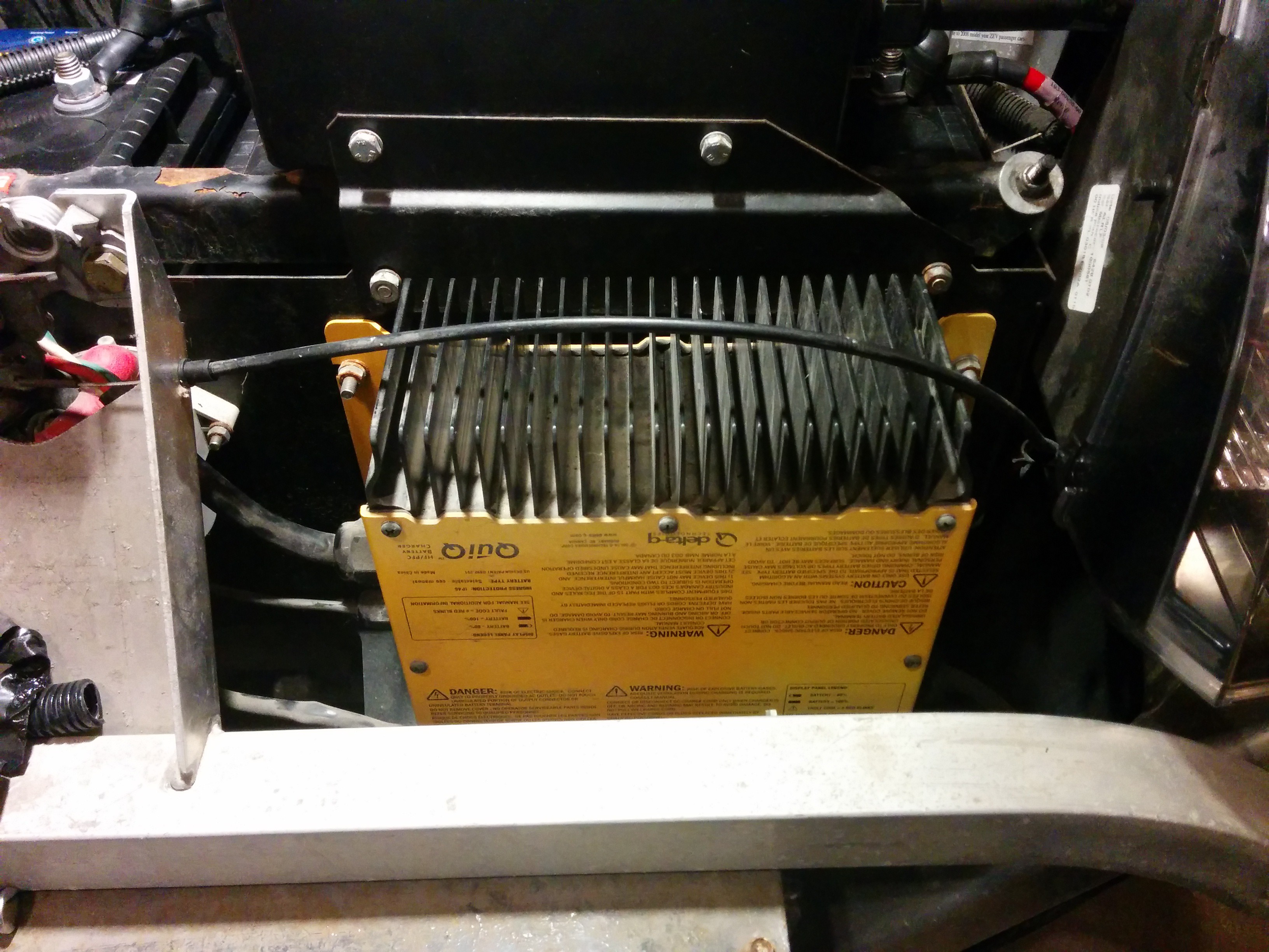
Disconnect the charger and unbolt from the car. The cables are kind of hard to get at, but aren't too bad. Watch the ground screw on the right-hand side.
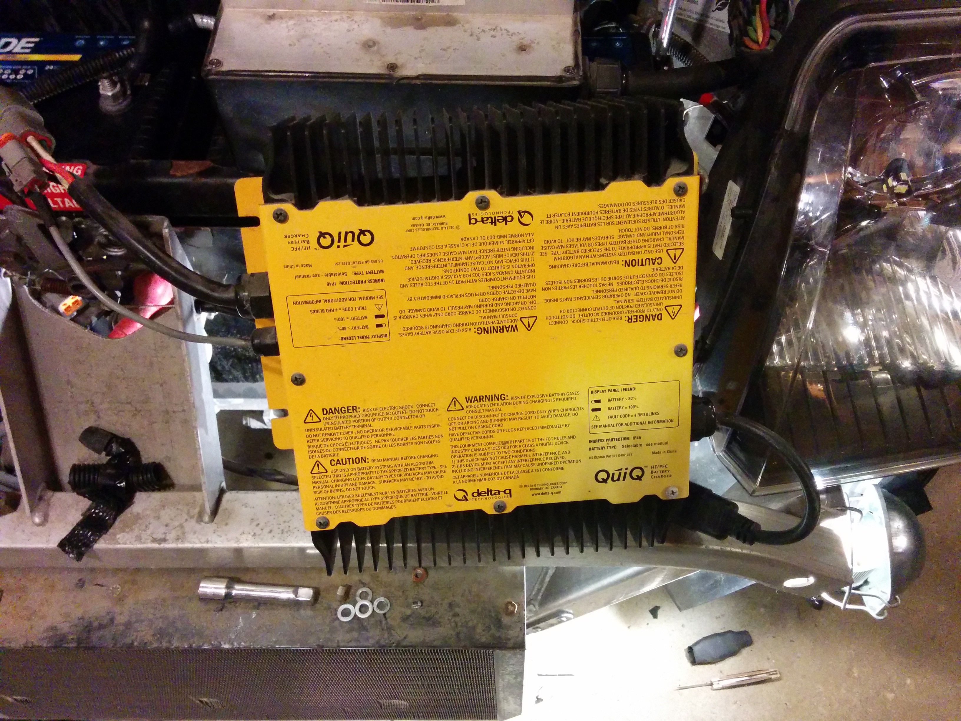
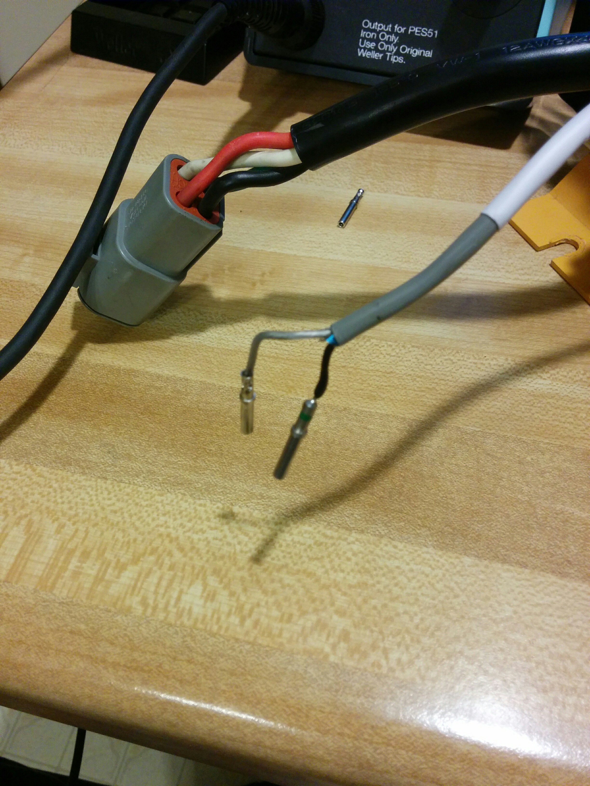
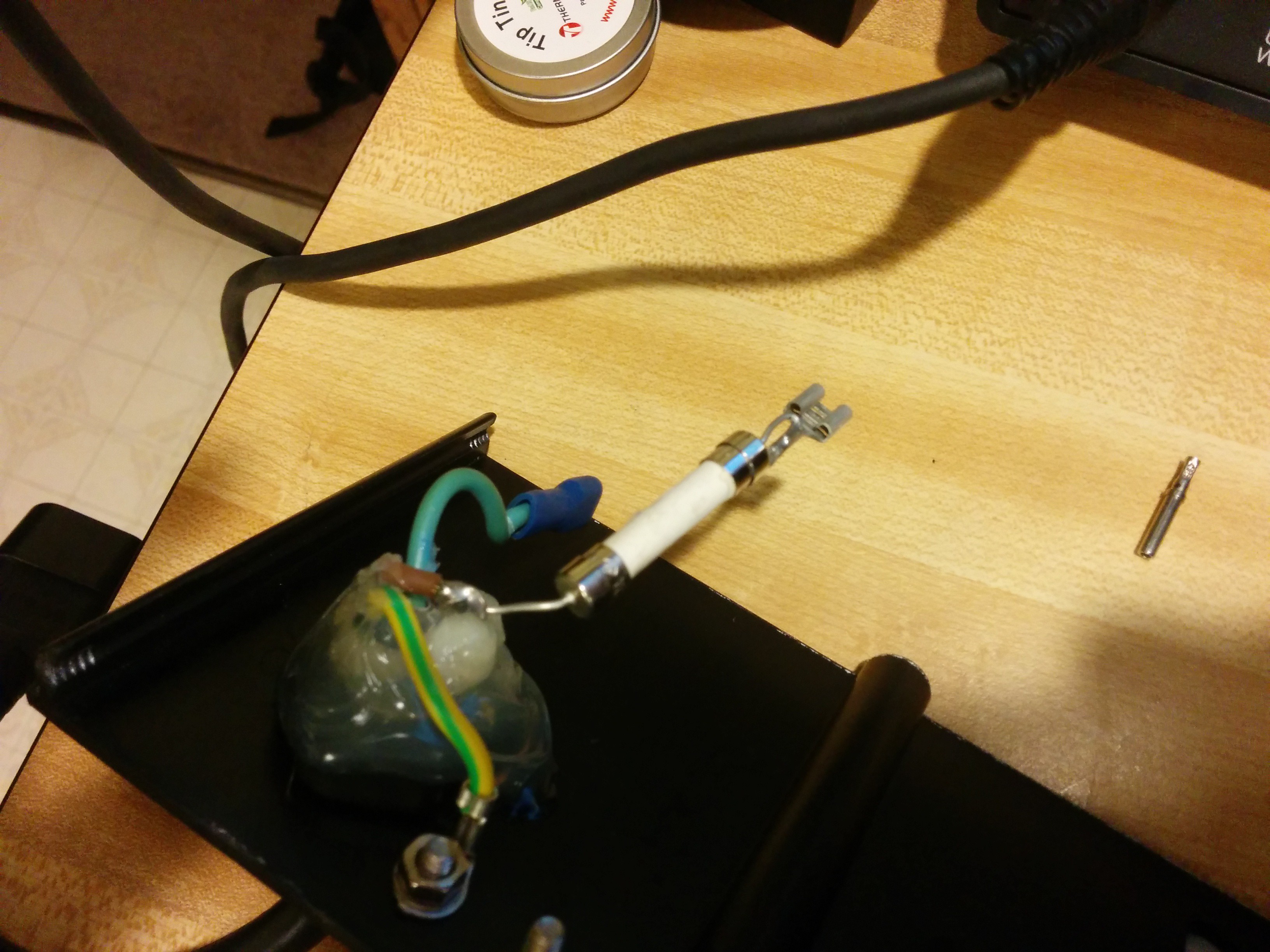
Once I had the charger disconnected from the car, I brought it inside for the next steps. When I did, I noticed that one of the connectors, what I believe to be the temperature sensor, was broken. In the picture below, it was the black wire on the smaller 2-pin connector. It broke from the pin in the plug. I'm unsure if this was like this before, or if it was caused when I removed the charger from the car. Either way, watch the wires, you don't want to break anything!
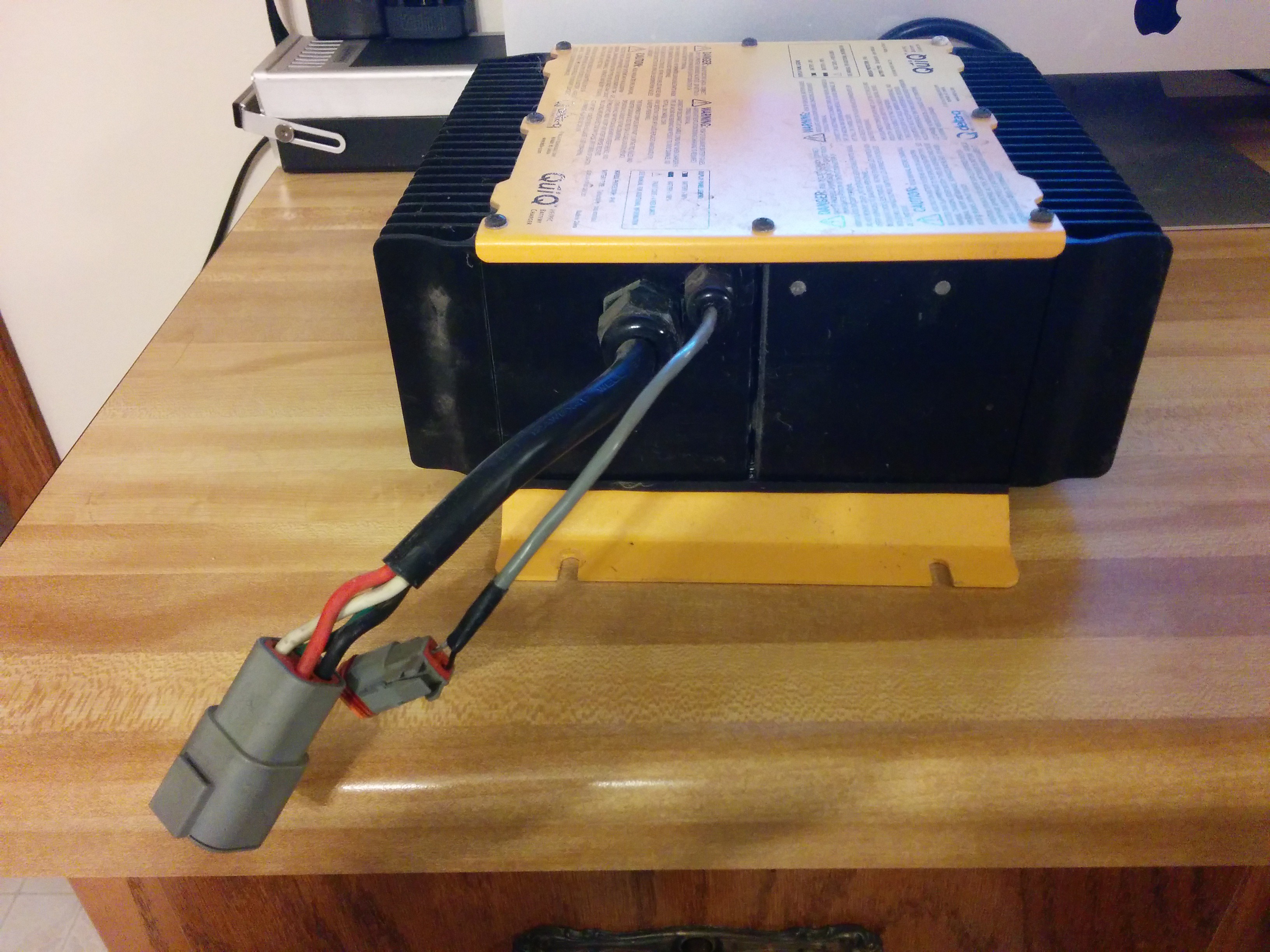
The connector is what is called a Deutsch plug. These are fairly easy to repair. There are YouTube videos online that describe how to take the plugs apart to get to the individual connectors. In my case, I removed the orange plastic end-cap, and then used a pick to pry up the plastic latches holding the individual pins in place, the orange silicone seal came along with the wires. It was a clean break at the pin.
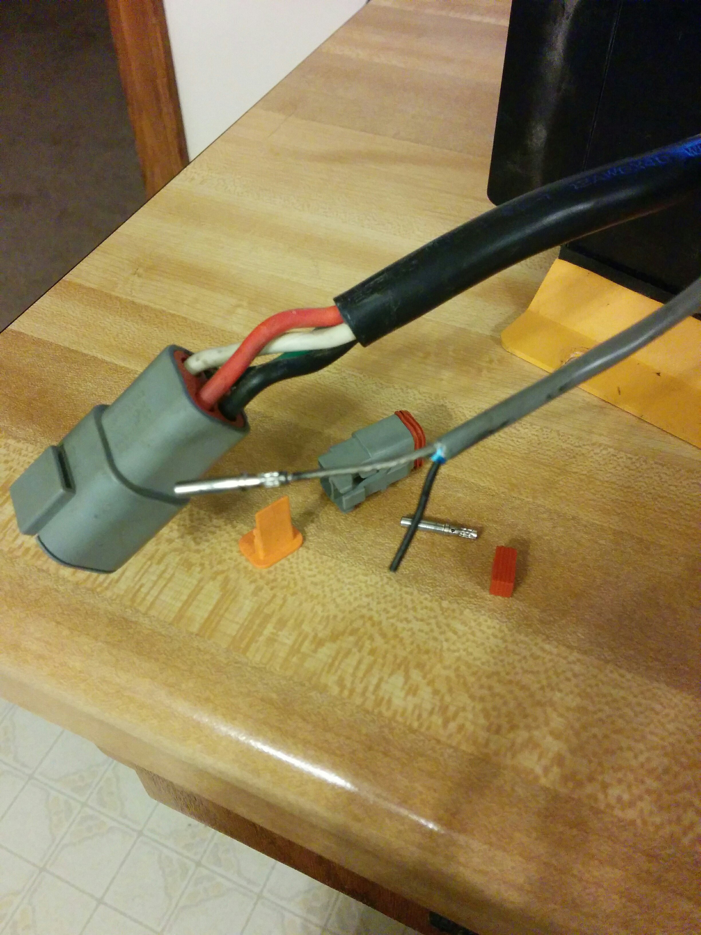
There are a lot of ways I could have fixed this particular plug. I could have just soldered the wire back onto the end of the connector. I could have attempted to re-crimp the wire on, or I could just replace the pin. Amazingly enough, I actually had one of these pins, but only one. I didn't have a crimper though. Deutsch plugs get crimped with a special 4 way circular crimper, which I did not have. So I simply stripped the wire back and soldered it into the end of the pin. While I was at it, I slipped some new heat-shrink tubing onto the wire for use later.
Once I had the new pin in place, I put the red seal back onto the wires and inserted the pins back into the plug in their original orientation.
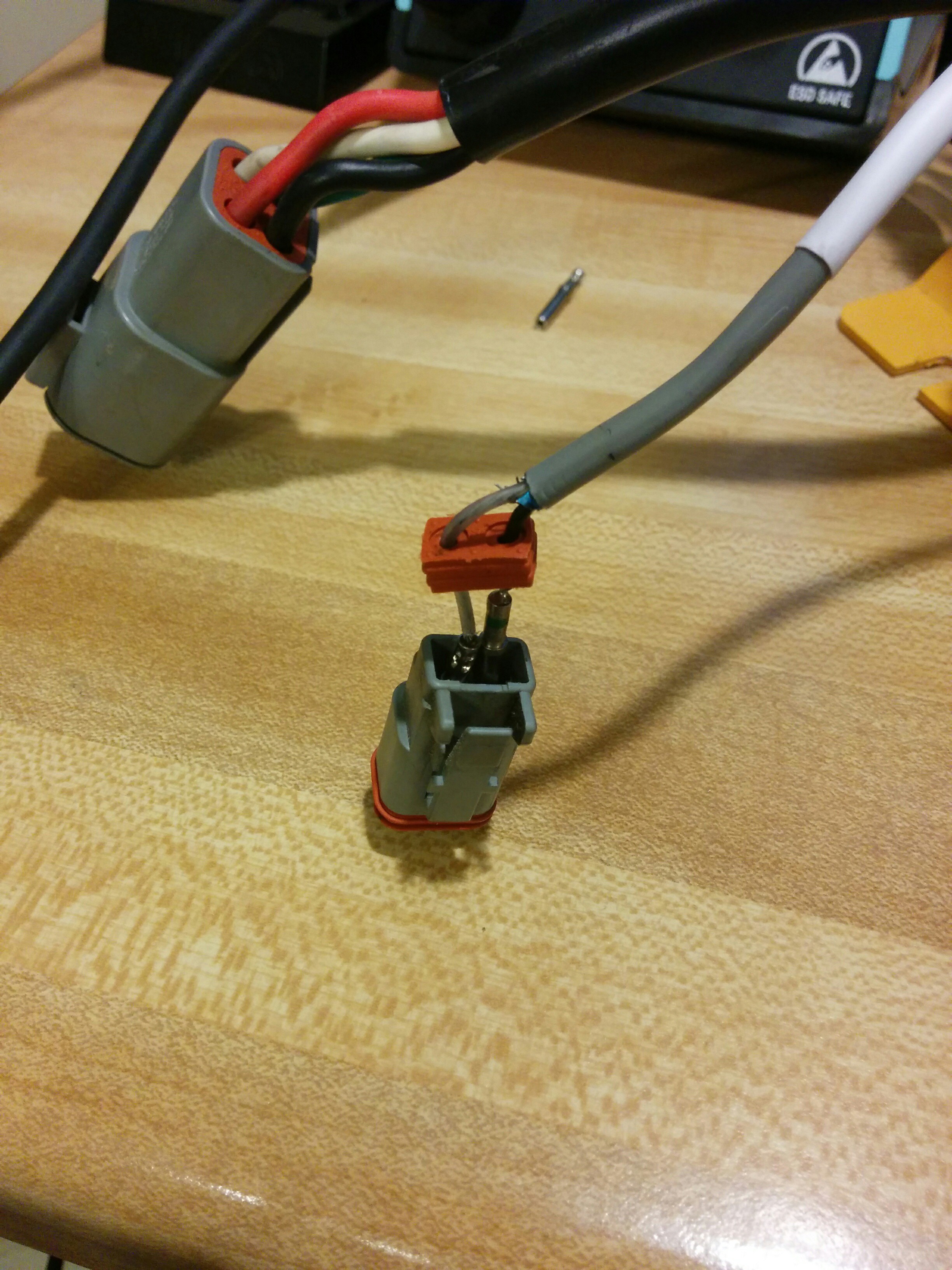
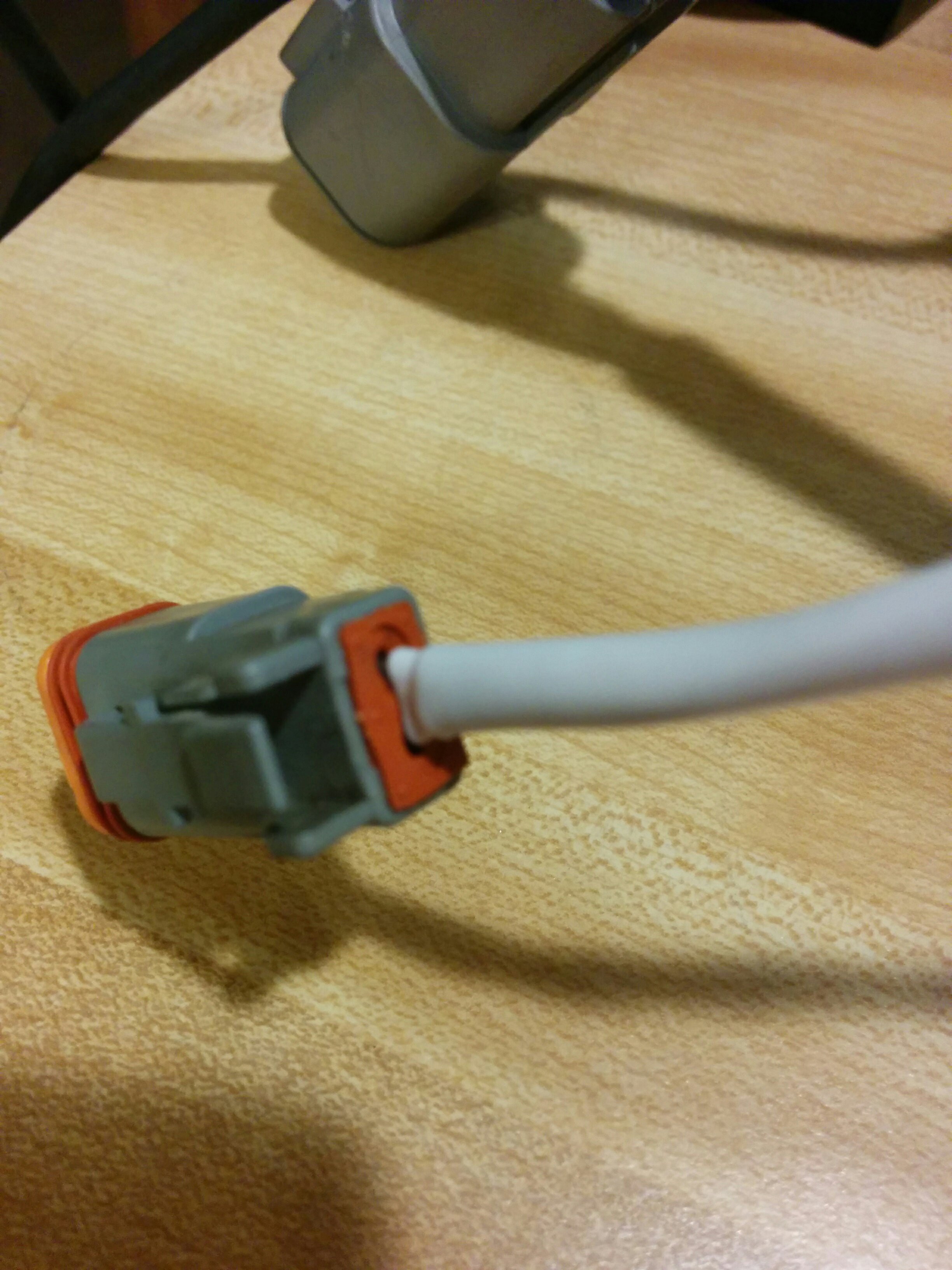
Once I had the pins in place, I put the orange end back onto the connector, shrunk the heat-shrink, and called it job well done. However, you can see that the wires are slightly different lengths now. I fixed that, once I was in the charger, by simply pulling the clear wire into the charger until it was the same length as the black wire.
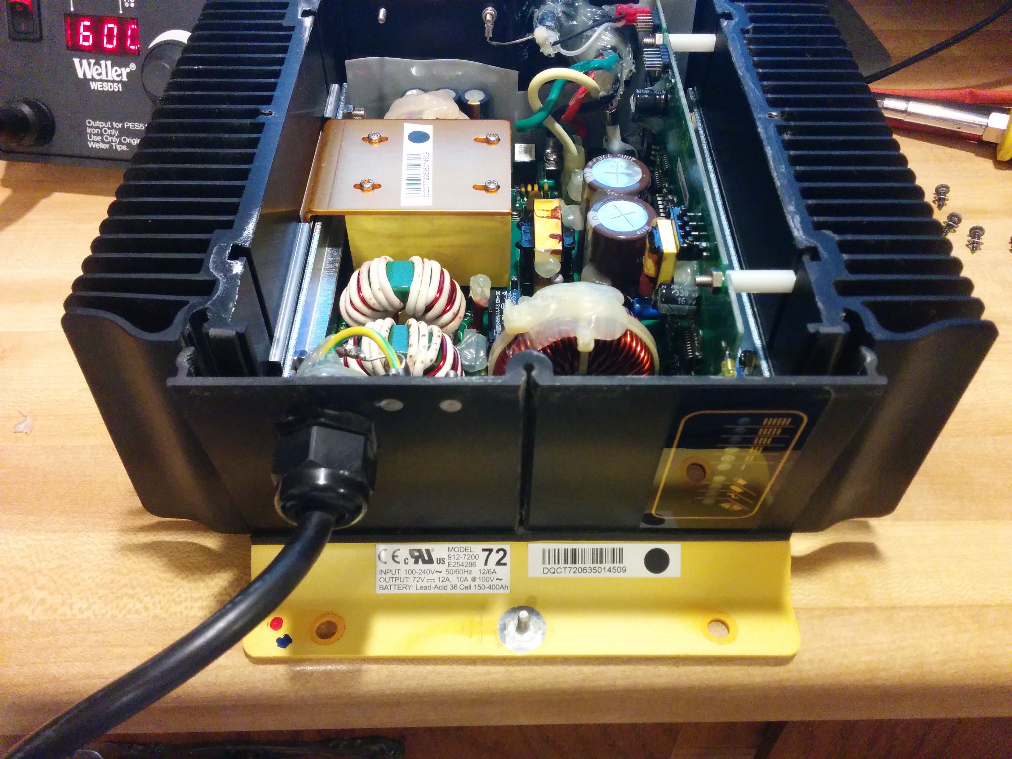
Now it was time for step #2, open the charger. Remove the eight Phillips screws on the top of the unit, and the yellow cover will come off. It has a foam gasket, so it may be slightly stuck to the body of the charger.
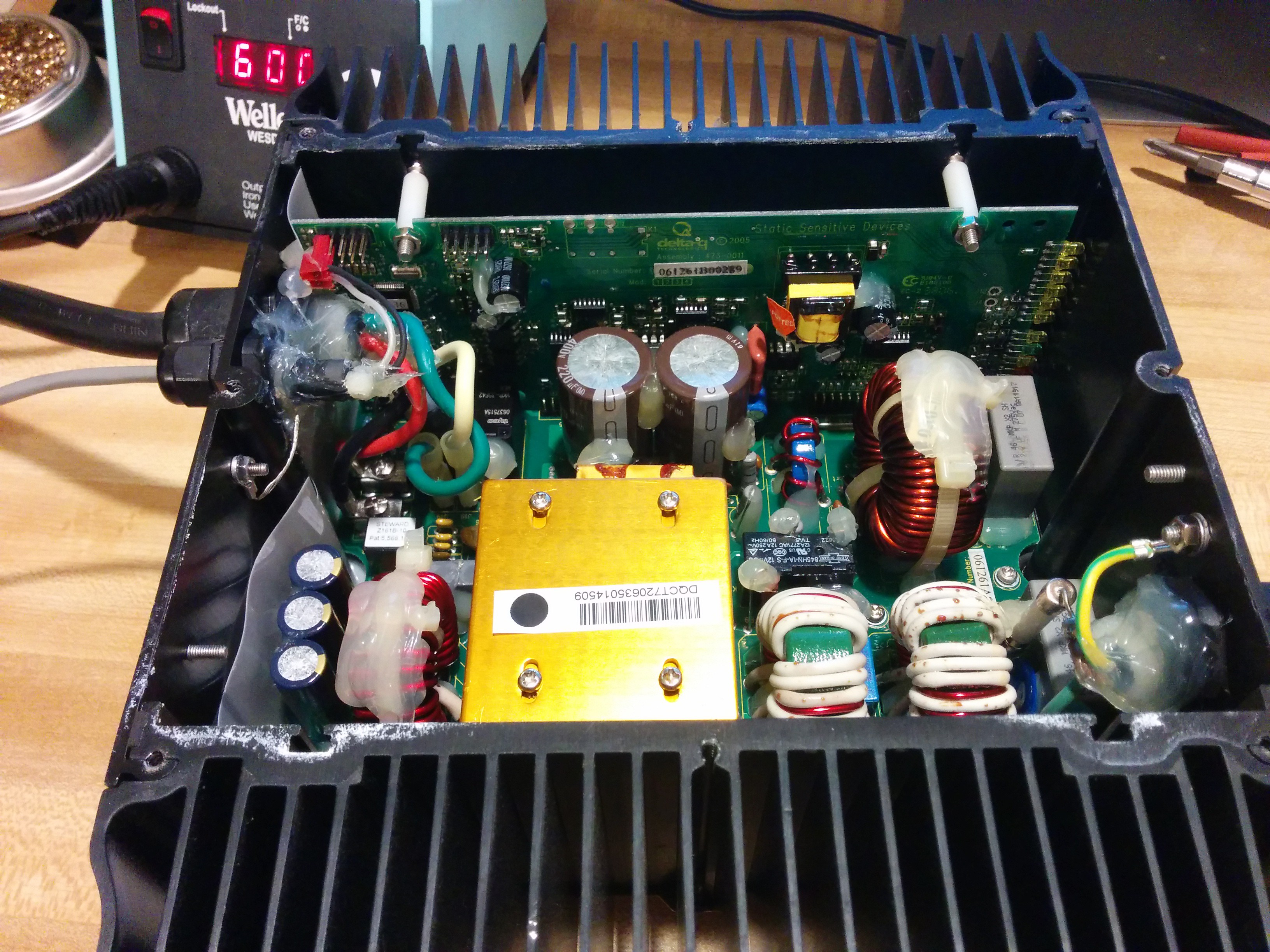
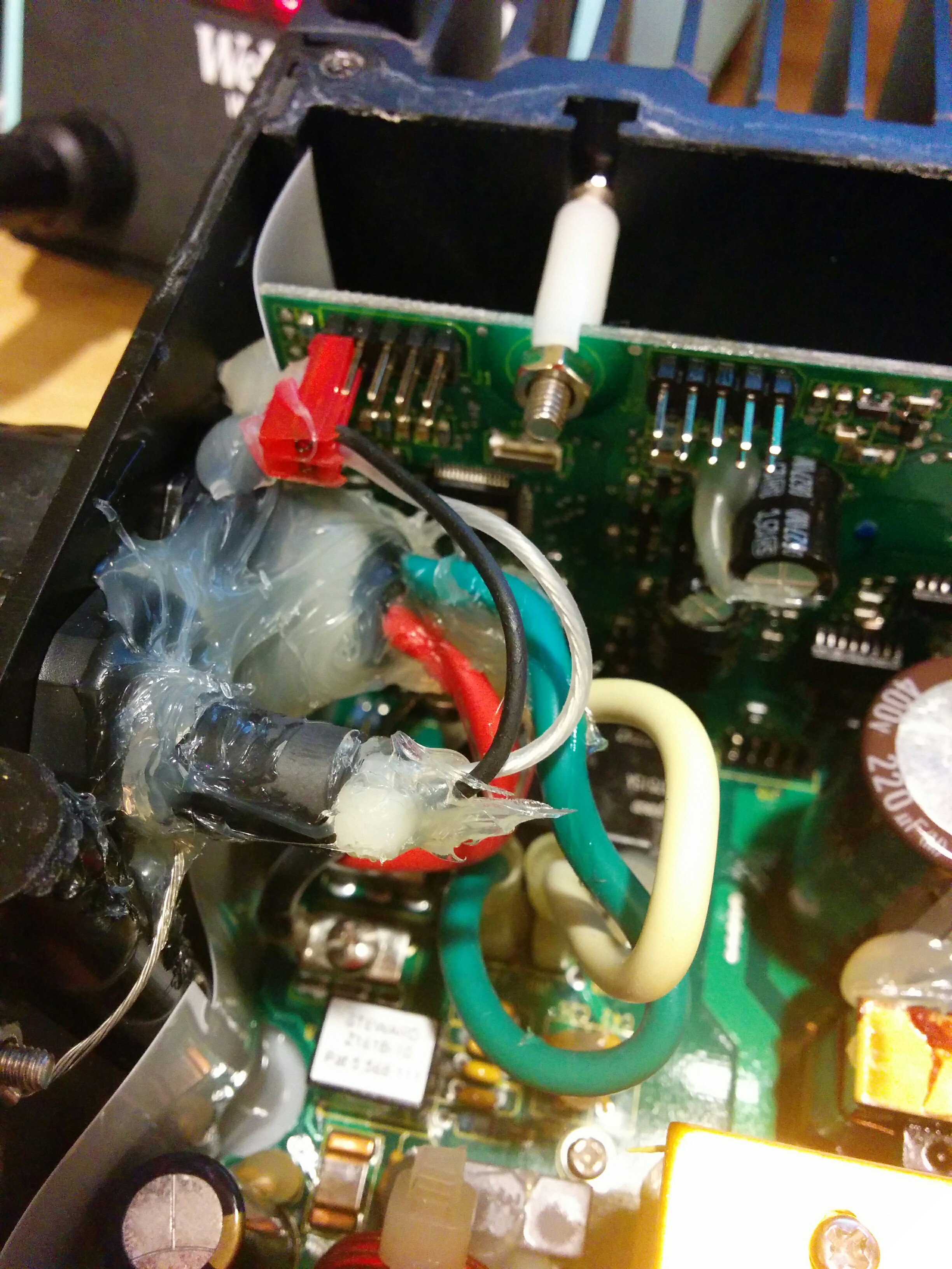
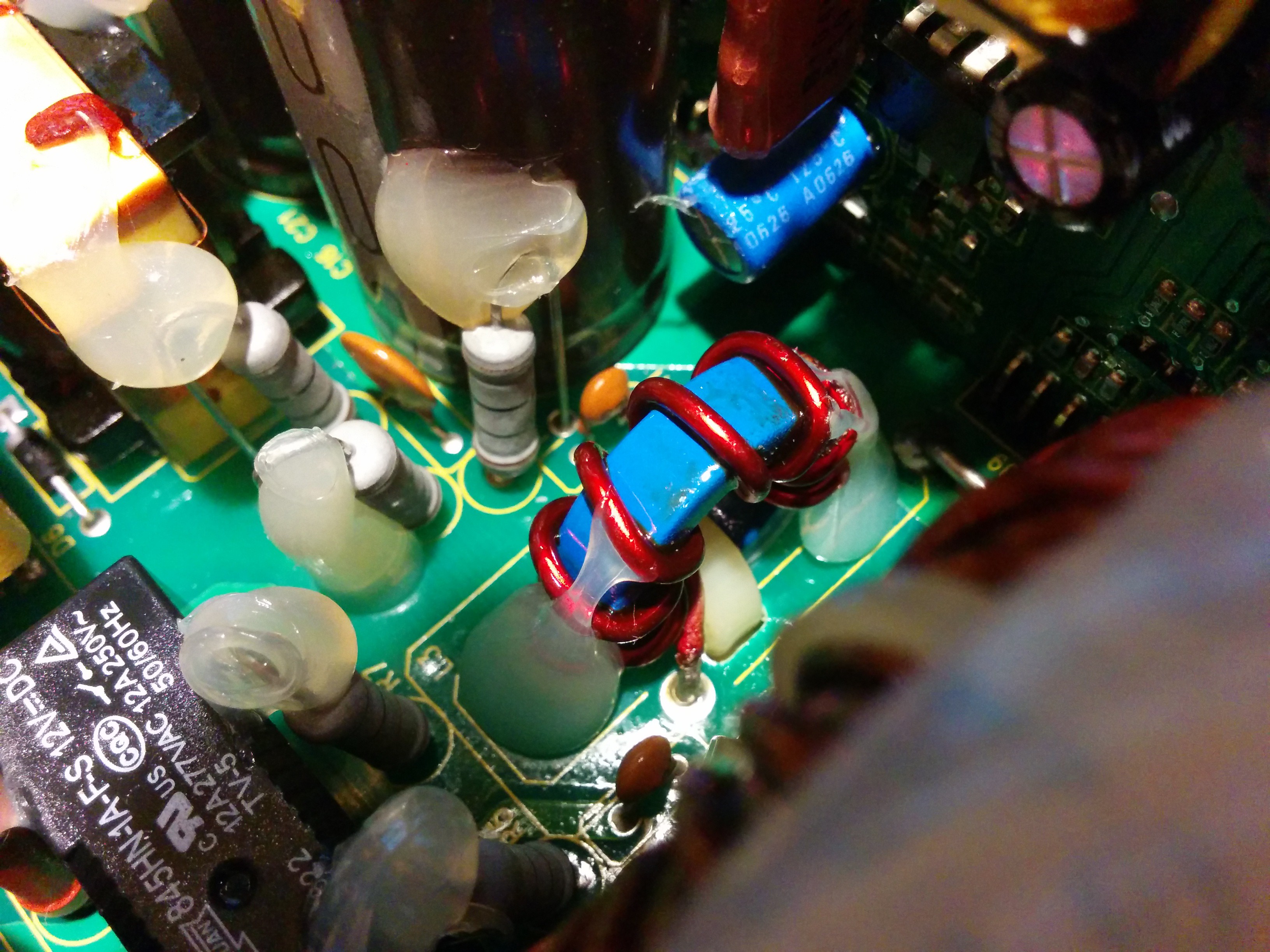
You can see the charge and sensor wires entering the charger on the top left and the AC wires entering on the lower right. There is also a lot of silicone all over the boards to help prevent damage from vibration.
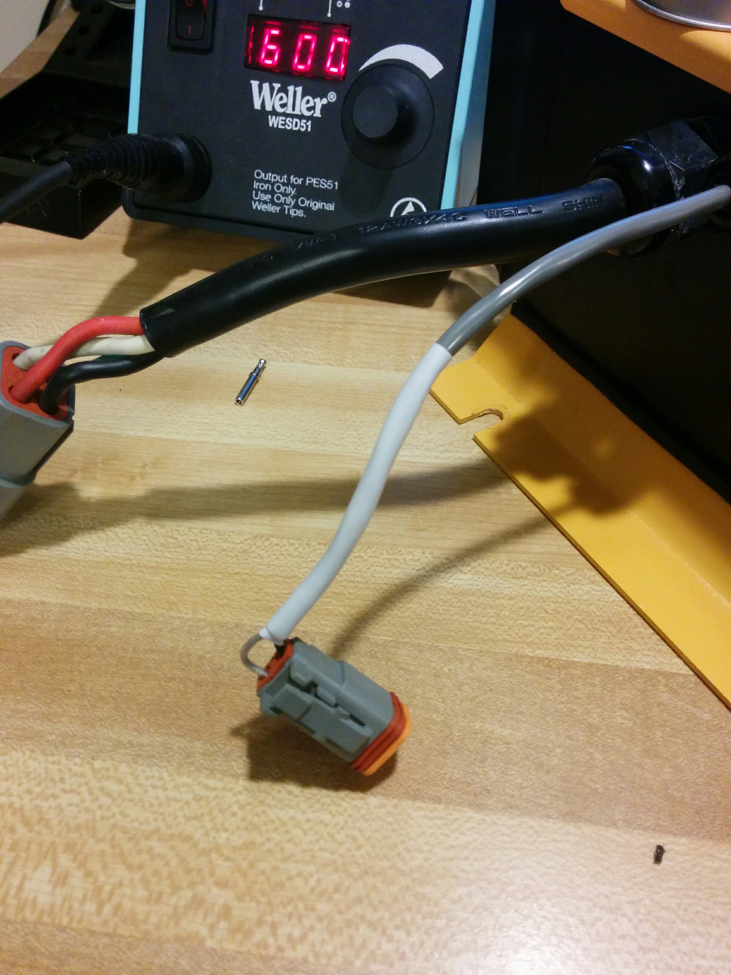
Like I mentioned earlier, I pulled the clear wire on the sensor cable so that it was even with the black wire on the plug end.
And this yielded a very nice looking sensor plug.
Now, onto step #3, removing the AC panel. There are three screws on the bottom of the charger on the right side with the AC input wire. Remove them.

This will then let the AC panel move around freely. Pull it slightly away from the rest of the charger.
At this point the original instructions say to rotate the panel to access the PC board. However, I found it just as easy to disconnect the AC input wires from the main PCB. There are only two (the ground is connected directly to the panel itself) and one of them is a fuse-plug contraption. Use a small pair of pliers to disconnect the female connectors from the male connectors on the PCB. Remember that the fused input (load) is on the right and the wire input (neutral) is on the left.
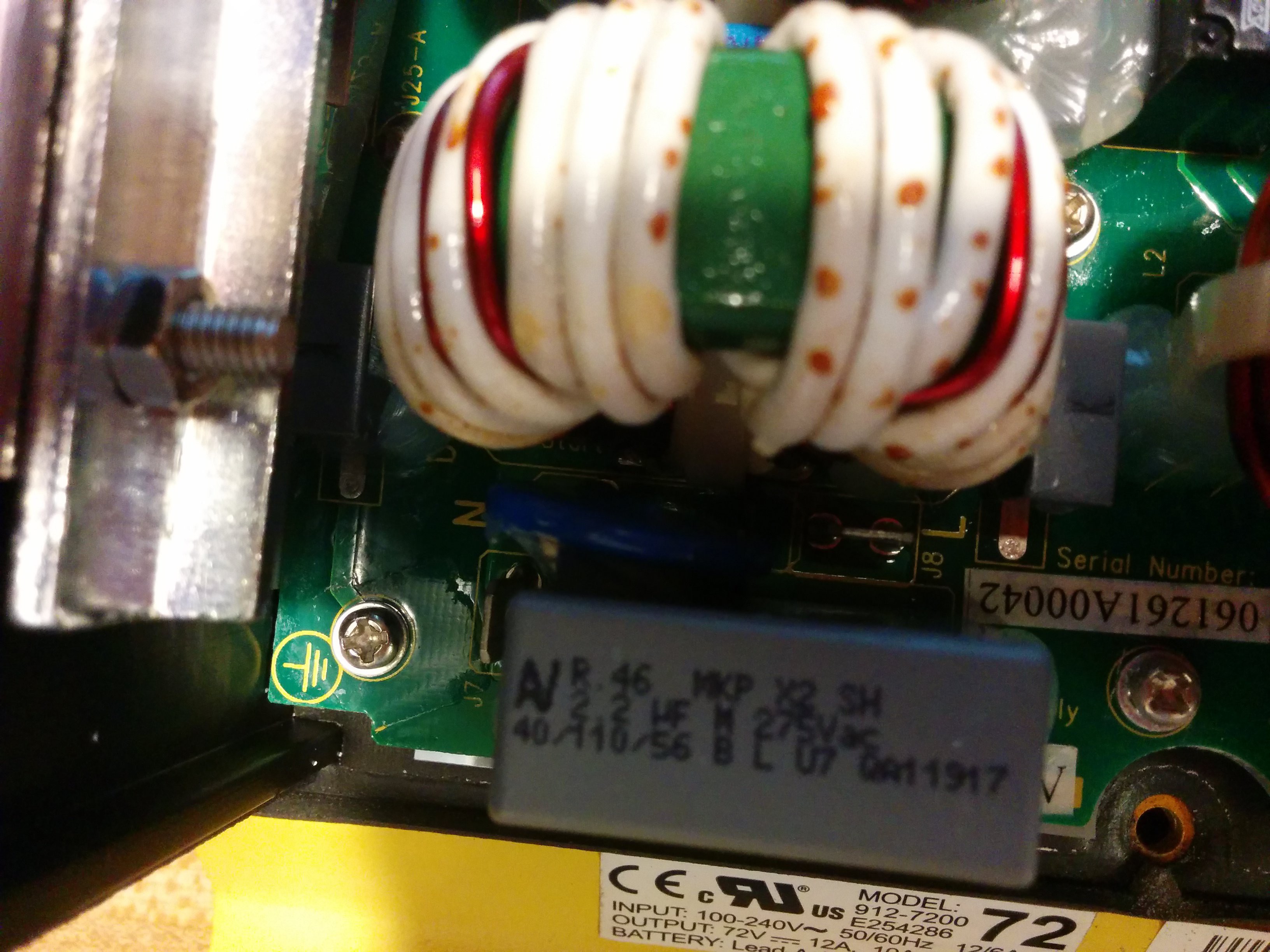
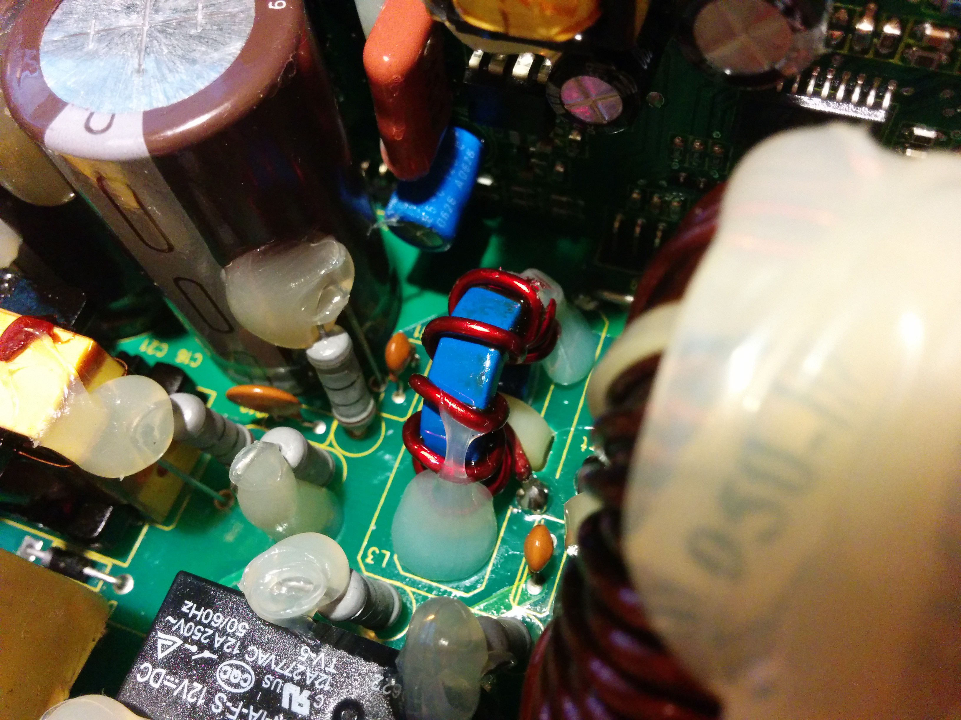
Now that the panel is disconnected, let's look at that shunt.
The shunt is located to the left of the vertical PCB on the main PCB and next to the huge coil. It simply looks like a heavy-gauge copper wire soldered into the PCB.

Finally, just like a Haynes manual, assembly is the reverse of disassembly.
Discussions
Become a Hackaday.io Member
Create an account to leave a comment. Already have an account? Log In.
Sewer camera helps you to find the https://www.techdee.com/best-essay-writing-service-review/ fault where your eyes cannot see. The good plumber always has this camera and it works well. The good company invest lots of money and need that everything will good. Thank you for sharing such useful information.
Are you sure? yes | no
Nice work!
Are you sure? yes | no