 Ken Yap
This is the successor to #TTL binary clock.
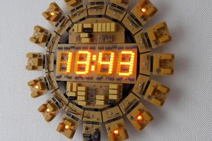
This clock counts minutes and hours in ternary, that is to say, each LED displays a trit (ternary digit). This is by using bi-colour LEDs which can represent 3 states, off = 0, red = 1 and green = 2. To count up to 60 we need 4 trits, which can represent from 0 to 3^4-1 = 80. To count up to 24 we need 3 trits which can represent from 0 to 3^3-1 = 26. To reset on overflow to 60 or 24 we use NAND gates to detect 60 = 2*3^3 + 2*3^1, and 24 = 2*3^2 + 2*3^1.
The basic trit counter, or flip-flop-flap (FFF), is made up of two halves of a 74LS74 dual flip-flop which goes back to 00 after 10, skipping the 11 state. This is done with a NOR gate as shown in this diagram of two trit counters. (You may also recognise this as a length 2 LFSR.) You can run this simulation of two FFFs in Falstad and see it cycle through the states from 0 to 8. The Falstad file as well as a Logisim model of the entire counter chain are in the GitHub repository.
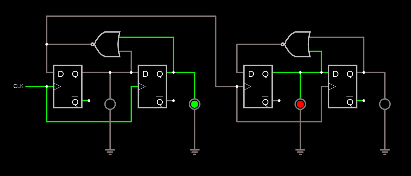
LEDs are driven directly from the 74LS74s as they only need a few mA current. We use the ~Q outputs since the LEDs are common anode and thus active low. This also avoids loading the Q outputs which are used for cascading and overflow detection.
The rest of the circuit is unremarkable. A CD4060 hosting a 32768 Hz crystal is the timebase, generating powers of two frequencies down to 2 Hz. This further divided by 120 with a 74LS393 to give a one-minute period square wave driving the trit chain. A couple of 74LS157s are directed by buttons to select higher frequencies to feed into the chain to rapidly advance minutes or hours.
The 74LS123 dual monostable may not be needed. It's there in case the pulse from the minutes and hours overflow is not wide enough to reset the minutes or hours FFFs. If not needed jumpers can be installed from 1-4 and 9-12.
Note that the 74LS393 advances on the falling edge of the clock input, whereas the 74LS74s advance on the leading edge. This means that were we displaying the seconds counter, it would actually advance the minute at the 40 second mark. But we are not, so it doesn't matter.
Parts were sourced from my junkboxtreasure store of old TTL chips, some dating back to the early 80s.
The board was fabricated by JLCPCB. As the board is 100x150 mm no cheap offers applied and cost was higher, though about the same as the shipping. The board is not critical as the highest frequency on it is 32768 Hz in the vicinity of the crystal (but which requires care over stray capacitances), or 1024 Hz in the outputs.
Chip utilisation
Those two 74LS157s which are only ¼ used could be replaced by one 74LS153 but I'm short of those. In addition half of the 74LS00 and 74LS08 is wasted, partly due to the 74LS393 reset being active high. But they are at opposite corners of the board so the traces would have been longer.
Firmware
What firmware? 🤣
Reading the clock
I'm sure I will get used to the numbers 1 2 3 6 9 18 27 54 and read the time quickly. Not so good for colour-blind people who have difficulty with red and green. However the green is brighter than red so that may help.
What is ternary about this clock?
Obviously I don't have 3-level logic so it's still binary logic at the hardware level. The flip-flop-flap is conceptually ternary even though it's realised with two 74LS74 flip-flops by wasting one state. The display is ternary, with 3 states, off, red, green. So it's only ternary at a couple of levels.
Was it worth it?
Aside from the novelty of a ternary readout, this could have been accomplished with any lowly microcontroller with 18 I/O pins, or even less if shift registers are used. I like using retro components much more if I don't have to buy them. I fancied getting those ancient chips back into service. I did it for the sake of the 74LS74s and I'm sticking to that story. 🤣
It will probably be my last circuit and PCB design with chips of that era. There'll be the odd project that...
Read more »
 Pierre-Loup M.
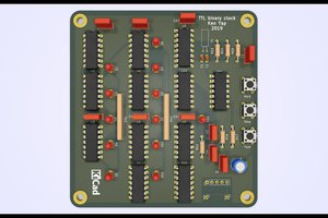
 Dave Gönner
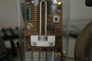
 Kris Slyka