-
Log 5: Coin Cell Example
08/24/2023 at 22:56 • 0 commentsNow let's look at one of the examples provided on the repo. This example is meant to represent a low-power system which operates from a coin cell.
# First, define all threads. This is how we define which components are on, how much current
    # they need, and how long they are on in different modes. All threads are periodic and run forever
    baro_thread = epm.Thread(name="Barometer", stages=[
        epm.Stage(delta_t_sec=0.002,components=[
            epm.Component(name="Barometer-BMP390",mode_name="Sample",current_ma=0.660),
            epm.Component(name="Microcontroller-ATSAML21",mode_name="Active",current_ma=0.6),
        ]),
        epm.Stage(delta_t_sec=0.03,components=[
            epm.Component(name="Barometer-BMP390",mode_name="Sleep",current_ma=0.0014),
            epm.Component(name="Microcontroller-ATSAML21",mode_name="Active",current_ma=0.6),
        ]),
        epm.Stage(delta_t_sec=10.0,components=[
            epm.Component(name="Barometer-BMP390",mode_name="Sleep",current_ma=0.0014),
            epm.Component(name="Microcontroller-ATSAML21",mode_name="Standby",current_ma=0.0025),
        ])
    ])
The ultra-low power microcontroller ATSAML21 is used alongside the barometer BMP-390. The operation is simple. There are three stages to the operation. In the first, the barometer is on and being sampled, and the microcontroller is active. In the second, the barometer is asleep and the microcontroller is active (performing some calculations on that data), and then in the third stage, both devices are in a sleep mode.
Next, let's look at how a regulator is defined!# Next, define all power rails based on their voltage regulators # Consider TPS7A02 reg_1v8 = epm.VoltageRegulator(name = "1.8V Rail", output_voltage=1.8, is_switching=False, threads=[baro_thread], quiescent_current_ma = 0.000025, max_current_output_ma=200.0)Here, we consider an ultra-low power regulator the TPS7A02. This is not a switching regulator. We set the voltage level at 1.8V, and provide the quiescent current and maximum current from the datasheet. After the latest updates, we connect threads to a regulator.
After defining the voltage regulator, the battery is defined.# Then, set up all sources and energy harvesting source = epm.LithiumCoinCellBattery(name = "210mAh, CR2032", number_cells=1,regulators=[reg_1v8],capacity_mAh=210.0,initial_charge_mAh=210.0, internal_resistance_ohm=60.0)This model is of a CR2032 coin cell. After the latest update, these tools include not just a lithium ion cell but also lithium primary coin cells. The difference is in the voltage vs. state of charge curve. After these updates, we attach regulators to a battery.
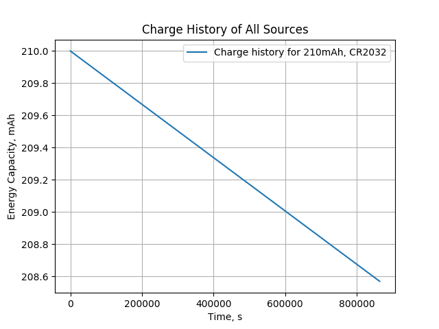
Finally, let's see how to setup the whole system and simulate!this_sys = epm.EmbeddedSystem(name="Coin Cell Example", sources = [source]) this_sys.power_profile(sim_time_sec=10*86400.0, record_time_history=True) this_sys.print_summary() this_sys.plot()After the latest updates, we attach a set of sources (batteries) to a system, and then can simulate for a configurable amount of time. The print summary method prints out some useful information about the net energy for each regulator and battery life for systems which do not recharge.
![]()
The plot method provides some useful plots which summarize the performance over the simulated time, such as the discharge status shown below.
![]()
-
Log 4: Major Update - Support for Multiple Sources and Multiple Buses
08/24/2023 at 22:36 • 0 commentsAfter not working on this project for a while, I came back to it for a couple major updates. All the updates are included on the repository here. Those features include:
- Your system can now have multiple batteries.
- Your system can have multiple voltage regulators connected to each battery.
- Your system can still, as before, have multiple threads running on each regulator (and each thread can have multiple components.
- The support for switching and linear regulators has been improved. Both have quiescent current included, and the switching regulator has a efficiency input.
- A few bugs were fixed, especially in the charging/discharging calculations.
- Each regulator has a maximum current, and the tool will warn you if your exceed that.
- There are helpful printing and plotting tools for each system you build.
- Two new examples are added: a low power device with a coin cell battery and no recharging and a multiple battery example which is more complicated and shows more capabilities.
For anyone estimating the power consumption or battery life of a system with multiple power modes , this tool is for you!
-
Log 3: A Simple Example
01/29/2022 at 21:58 • 0 commentsThe code snippets below provide a complete example. First, we must define the threads and their components and rated power.
accel_thread = epm.Thread(name="Accelerometer Sampling", stages=[
        epm.Stage(delta_t_sec=0.5,components=[
            epm.Component(name="ESP32",mode_name="Active",current_ma=100.0),
            epm.Component(name="Accelerometer",mode_name="Active",current_ma=1.5)
        ]),
        epm.Stage(delta_t_sec=20.0,components=[
            epm.Component(name="ESP32",mode_name="Sleep",current_ma=0.05),
            epm.Component(name="Accelerometer",mode_name="Sleep",current_ma=0.001)
        ])
    ])

led_thread = epm.Thread(name="LED", stages=[
        epm.Stage(delta_t_sec=0.1,components=[
            epm.Component(name="LED",mode_name="On",current_ma=5.0)
        ]),
        epm.Stage(delta_t_sec=4.9,components=[
            epm.Component(name="LED",mode_name="Off",current_ma=0.0)
        ])
    ])
Next, we build the system, with its threads, battery, and energy harvesting. Finally, we calculate the power profile for 3 days while saving the outputs. By default, total net energy will be reported but time histories are not.
this_sys = epm.EmbeddedSystem(name="Test", threads=[accel_thread,led_thread],
        energy_storage=epm.LithiumBattery(number_cells=1,capacity_mAh=1000.0,current_charge_mAh=500.0,internal_resistance_ohm=0.065),
        voltage_reg=epm.VoltageRegulator(efficiency=0.8),nominal_voltage=3.3,
        energy_harvesting=epm.SolarPanel(rated_power_W=1.5,t_offset_sec=0.0))


this_sys.power_profile(3*86400.0, True)
That's it!
-
Log 2: Battery, Regulator, and Solar Energy Harvesting
01/29/2022 at 21:52 • 0 commentsSummary
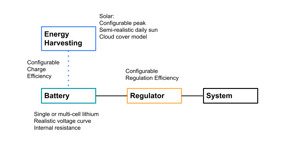
These modeling tools follow the block diagram shown below. All of the threads combine to form the "system." This is powered from battery through a regulator. Future features may be added to support more complicated topologies, but this covers many, many designs. The regulator is simple. Currently it simple has a single efficiency number, where 0% corresponds to a linear regulator and 100% efficiency corresponds to an ideal switching regulator. No dynamics, dropout, maximum current capability, efficiency vs. current curve, or other capabilities are currently implemented. Some of these may be added in the future
![]()
BatteryCurrently, single and multi-cell lithium batteries are supported. The user selects the number of cells, rated capacity, charge level at the start of simulation, and internal resistance. As the simulation progresses, the battery is charged and discharged. It cannot be charged more than full. This is obvious, but important and sometimes ignored by novices when specifying solar powered systems -- energy can be wasted if there is nowhere to store it. A piecewise linear typical discharge curve is provided, so approximate voltage levels can be seen.
![]()
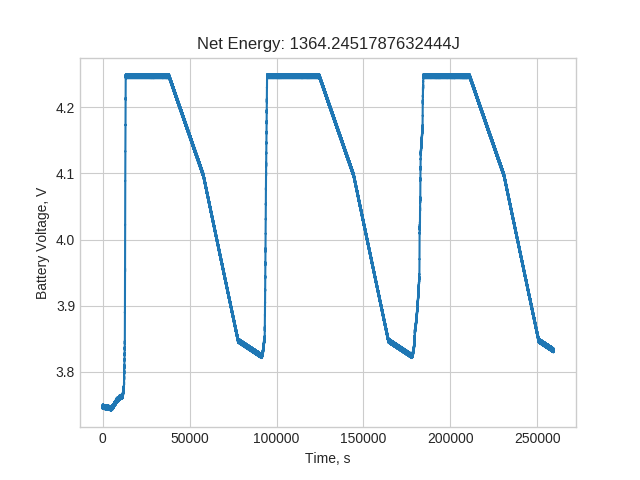
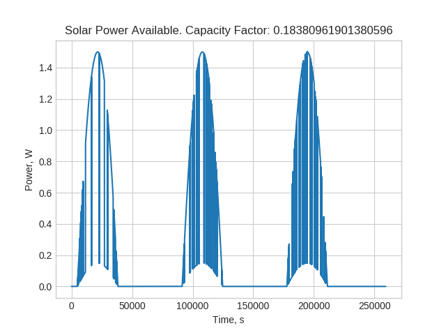
Solar Energy Harvesting ModelThe solar energy model is fairly simple but still capable of representing many real-world phenomena. The user provides a rated power of the panel, which is meant to represent maximum realistic power. Depending on the orientation of the solar panel, this may not be equal to the datasheet value. A very simple peak possible power curve is provided for now, as shown below. The time offset and alpha values can be used to shift the time and season, respectively.
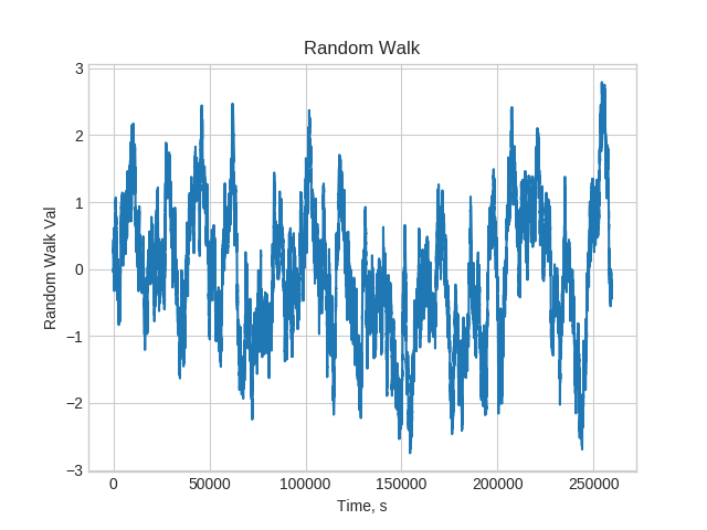
A simple model for cloud cover is also included. The available power is reduced to 10% of the sunlight if under clouds. This is a reasonable value based on my SOL sensor. The presence of cloud cover is determined by whether or not the absolute value of an exponentially correlated random walk process is outside of some set bounds. This process is set up as follows, where g is drawn from a normal distribution with zero mean and standard deviation of one.
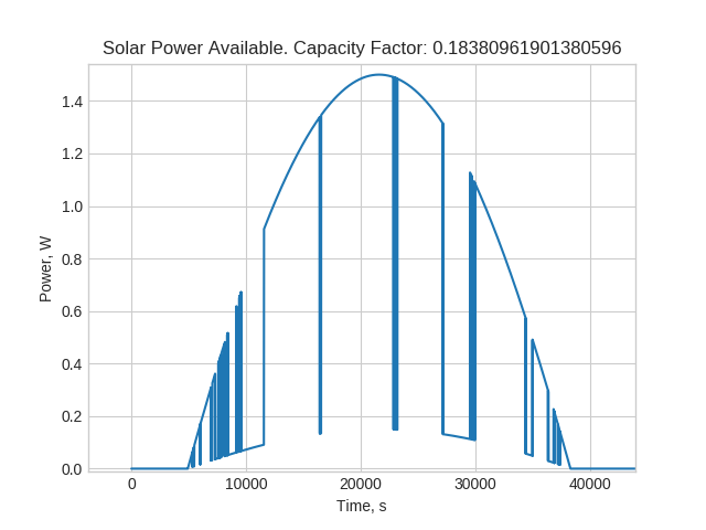
The time constant can be used to tune the frequency of clouds, and the threshold value can be used to adjust how much of the day is covered by clouds. The random walk process and corresponding solar power profiles are shown next.
![]()
![]()
![]()
-
LOG 1: How Components and Threads Work
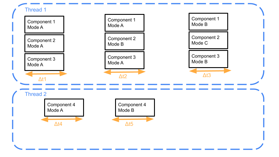
01/29/2022 at 21:16 • 0 commentsThe power consumption model considers as number of components with specified nominal current consumption. These components are spread out among any number of independent threads. Each thread can have any number of stages. Each stage has a configured length of time that it should run for. All threads repeat periodically. This setup mimics an embedded system running an RTOS, with scheduled tasks and interactions with external components. For example, an LED may be toggled at a prescribed frequency with some set on time. It can be given its own thread so that timing can be separate from other power consumption considerations. As another example, consider a sensor which is sampled every 10 seconds, then placed into a low power mode between samples. This can be readily supported in this thread representation. The image below shows this representation.
![]()
The implementation is straightforward. The user must know nominal current consumption of each component in each mode, and the timing between each stage. Currently, it is assumed that all components operate on the same voltage, but that may be changed in the future to allow for separate power buses to be considered. The code snippets below show how two separate threads are built. Here, some accelerometer is periodically sampled by an ESP32, and both the ESP32 and accelerometer enter sleep modes between the sampling. An led thread is created separately.
import embedded_power_model as epm

accel_thread = epm.Thread(name="Accelerometer Sampling", stages=[
        epm.Stage(delta_t_sec=0.5,components=[
            epm.Component(name="ESP32",mode_name="Active",current_ma=100.0),
            epm.Component(name="Accelerometer",mode_name="Active",current_ma=1.5)
        ]),
        epm.Stage(delta_t_sec=20.0,components=[
            epm.Component(name="ESP32",mode_name="Sleep",current_ma=0.05),
            epm.Component(name="Accelerometer",mode_name="Sleep",current_ma=0.001)
        ])
    ])

led_thread = epm.Thread(name="LED", stages=[
        epm.Stage(delta_t_sec=0.1,components=[
            epm.Component(name="LED",mode_name="On",current_ma=5.0)
        ]),
        epm.Stage(delta_t_sec=4.9,components=[
            epm.Component(name="LED",mode_name="Off",current_ma=0.0)
        ])
    ])
Electronics Power and Energy Modeling Tool
Python tools for predicting a design's power consumption over time. Support for battery models and energy harvesting such as solar power.