 otterpopjunkie
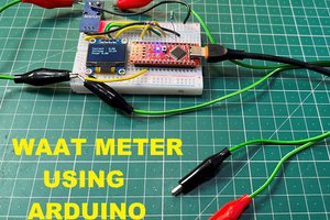
WIRING CONNECTIONS:
// Activation switch - D5
// SD ADAPTER:
// GND
// VCC - 5V
// MISO - D12
// MOSI - D11
// SCK - D13
// CS - D10
// INA219:
// VCC - 5V or 3V3
// GND - COMMON GROUND
// Scl - A5
// Sda - A4
// External:
// Vin- Power IN (or Voltage tap - V is monitored related to GND)
// Vin+ Power OUT (in series ONLY)
// GND - to Common Ground
---------------------------REFERENCES ----------------------------
// https://learn.adafruit.com/adafruit-ina219-current-sensor-breakout/wiring
// https://diyi0t.com/ina219-tutorial-for-arduino-and-esp/
// https://learn.adafruit.com/adafruit-data-logger-shield/using-the-real-time-clock-3
// https://github.com/flav1972/ArduinoINA219
--------------------------- CODE AS FOLLOWS -----------------------------
#include <SPI.h>
#include <SD.h>
#include <Wire.h>
#include <INA219.h>

INA219 monitor;

// CONSTANTS and VARIABLES:
const int chipSelect = 10;
#define LOG_INTERVAL 1 // ms between entries
#define SAVE_INTERVAL 15000 // ms between data flushes to SD card
#define Switch 5    //switch connected to pin
bool active = HIGH;  //switch to record or not
File logfile;   //SD card file reference thing
uint32_t syncTime = 0; // time of last sync()
uint32_t START_TIME = 1; //variable to record when logging starts

// set up variables using the SD utility library functions:
Sd2Card card;
SdVolume volume;
SdFile root;

void setup() {
  pinMode(Switch, INPUT_PULLUP);  //initialize activation switch input pin

  // Open serial communications and wait for port to open:
  Serial.begin(9600);
  while (!Serial) {
    ; // wait for serial port to connect. Needed for native USB port only
  }

  Serial.print("Initializing SD card...");
  if (!SD.begin(10)) {
    Serial.println("initialization failed!");
    while (1);      //if initialization fails it goes into an infinite loop (ded)
  }
  Serial.println("initialization done.");
  // open the file. note that only one file can be open at a time,
  // so you have to close this one before opening another.
  char filename[] = "LOGGER00.CSV";   //moved earlier so filename is global
  for (uint8_t i = 0; i < 100; i++) {
    filename[6] = i / 10 + '0';
    filename[7] = i % 10 + '0';
    if (! SD.exists(filename)) {
      // only open a new file if it doesn't exist
      logfile = SD.open(filename, FILE_WRITE);
      break;  // leave the loop!
    }
  }

  Serial.print("Logging to: ");
  Serial.println(filename);
  logfile.println("Time (ms),voltage (V),current (mA)");  //These are the headers for what's being logged.

  monitor.begin();    //this initializes the INA219 circuit.
  // setting up our configuration
  //  monitor.configure(INA219::RANGE_16V, INA219::GAIN_2_80MV, INA219::ADC_64SAMP, INA219::ADC_64SAMP, INA219::CONT_SH_BUS);

  // calibrate with our values
  //  monitor.calibrate(SHUNT_R, SHUNT_MAX_V, BUS_MAX_V, MAX_CURRENT);


}

void loop(void) {

  if (active == LOW) {   //if switch is on (pulled to GND), then run logger for duration.

      // log milliseconds since starting
      uint32_t m = (millis()-START_TIME);
      logfile.print(m);           // milliseconds since start
      logfile.print(", ");

      float VOLTAGE = monitor.busVoltage();  //GET VOLTAGE READING
      float CURRENT = monitor.shuntCurrent() * 1000;    //GET CURRENT READING in Amps
      logfile.print(VOLTAGE, 3);
      logfile.print(", ");
      logfile.println(CURRENT, 1);

//        Serial.print("shunt current: ");
//        Serial.print(monitor.shuntCurrent() * 1000, 1);
//        Serial.print(" mA     ");
//        Serial.print("bus voltage:   ");
//        Serial.print(monitor.busVoltage(), 3);
//        Serial.print(" V     ");
//        Serial.print(m);
//        Serial.println("ms");

      // delay for the amount of time we want between readings
      //delay((LOG_INTERVAL -1) - (millis() % LOG_INTERVAL)); //Verify this code later, maybe just add...
Read more »
 Sagar 001
 Gary
Gary
 Andy
Andy
 Vishwas Navada B