 Daniel Karpantschof
Opening the Advisor is super easy. It is built super robust, but also very easy to service.
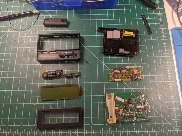
In the left column you'll find the front, including the LCD display (DUREL 65R62890A02 5277 // 51052-E01).
In the right column, from the top, you'll find the backplate, with vibration motor and to spring connections, the comms board with POCSAG decoder, and at the bottom the mainboard and AAA battery holder.
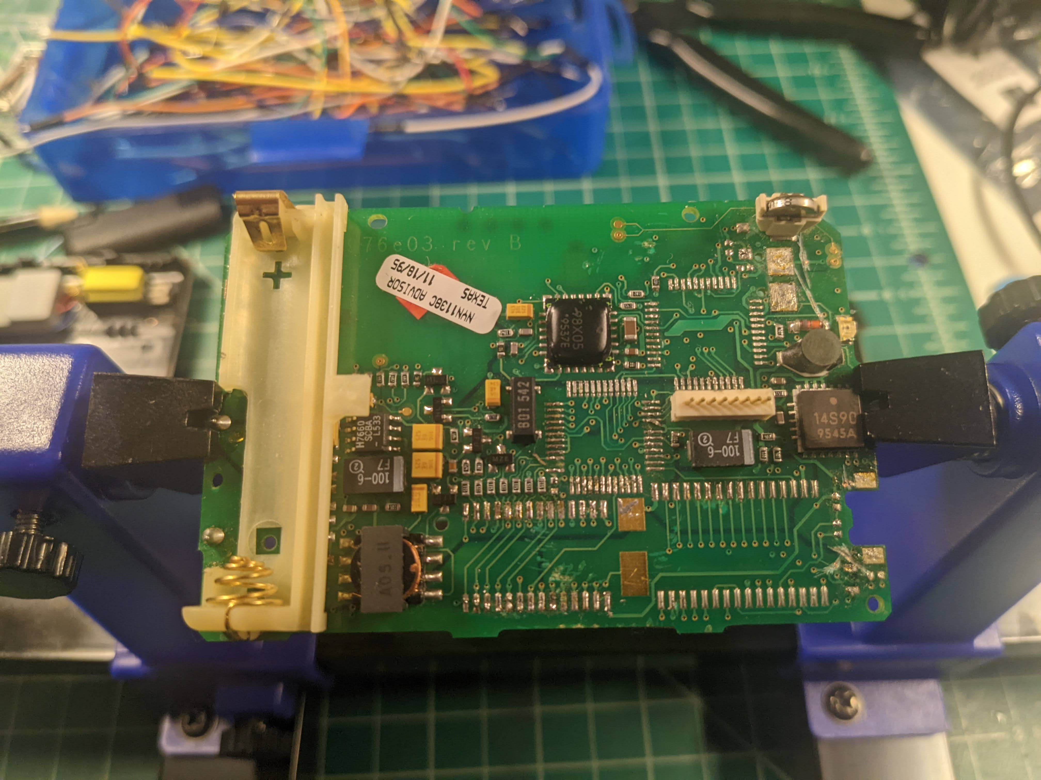
PCB Front
The front of the main PCB holds the pads for the membrane buttons. From left to right:
- Green Selection Key
- Red Escape Key
- D-Pad Left
- D-Pad Up
- D-Pad Down
- D-Pad Right
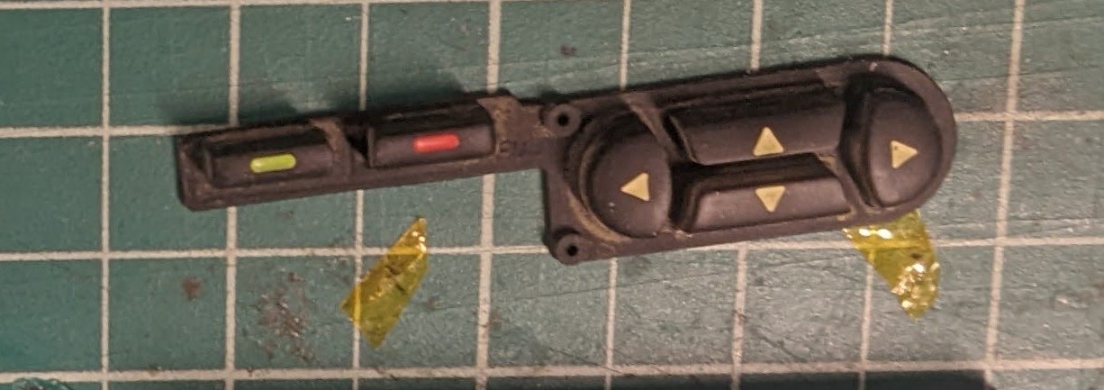
In the upper right corner you will find a cutout of the PCB to hold a small momentary switch for the main function key/power key
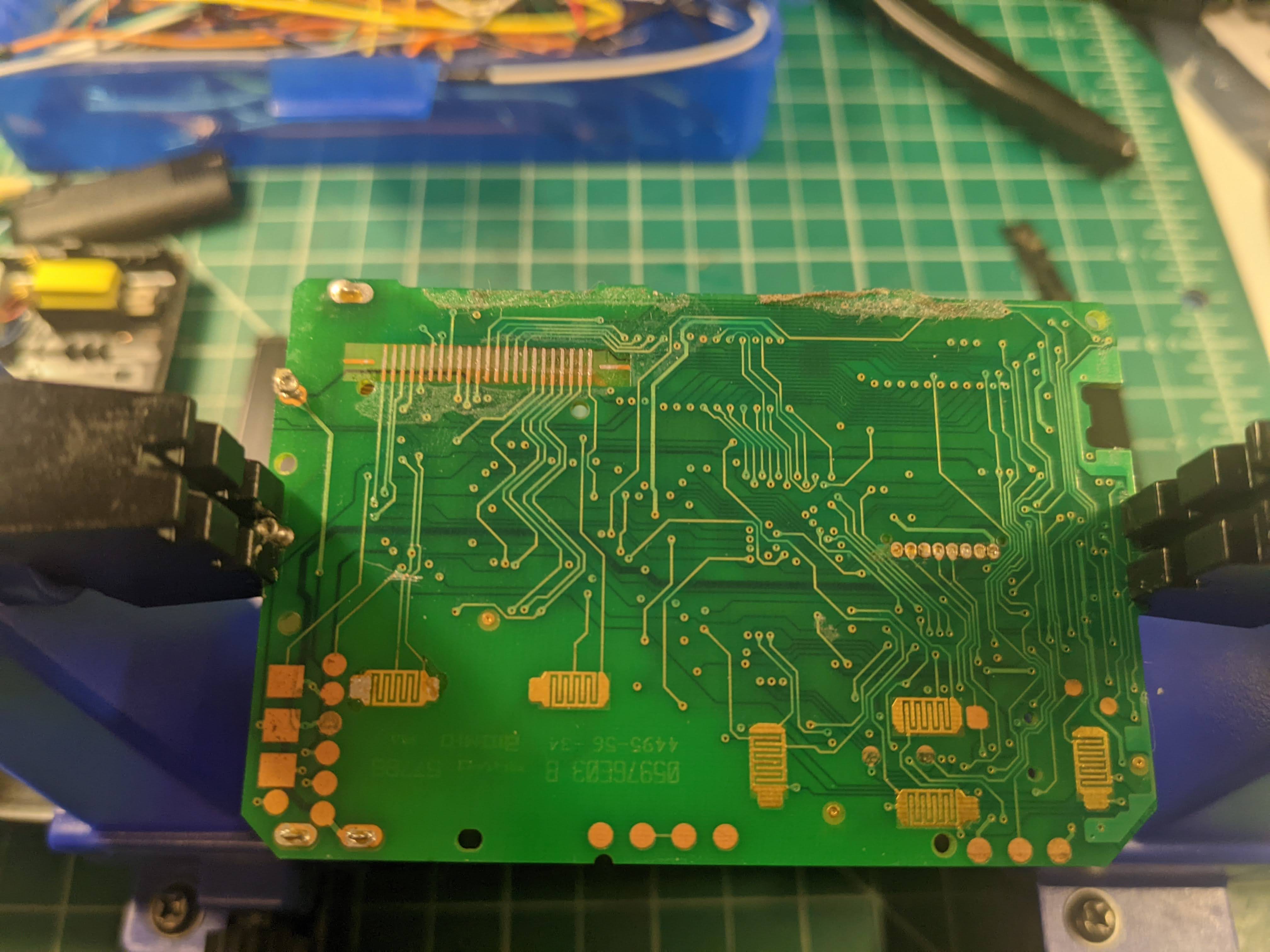
PCB Back
Notice: I've removed most of the ICs on the board.
The back holds the battery on the left. The white header in the middle, towards the right, is for the comms board.
There is a backup battery in the upper right corner, and just south of that, you will find the two solder pads for the piezo beeper (removed). Southeast of that is the onboard red LED and immediately south of that the cutout and two pads for the power button. West of that are two large pads for the connection to the vibration motor.
A more in-depth teardown can be found here: https://goughlui.com/2016/01/15/tech-flashback-motorola-advisor-pocsag-5121200bps-pager/ as well as how to reprogram the POCSAG board -- if that's your jam
Discussions
Become a Hackaday.io Member
Create an account to leave a comment. Already have an account? Log In.