In the last log I complained about the 68901 MFP chip and the issues I was having with its UART in particular (spoiler alert: it was my fault). The issue of general unreliability and random crashing is definitely one of the hardest types to debug, but it also indicates to me that it's probably not actually the fault of the MFP since it's not failing in a repeatable way.
There were two problems I was seeing:
- The UART is dropping bytes when transferring text and programs from the host PC to Mackerel.
- Occasionally, the whole system will just lock up in the middle of a long running program.
Testing the Programmable Logic
I figured the best place to start was to make sure all of my CPLD logic was correct. Aside from the address decoding which is trivial to test, the CPLD is also generating a /BOOT signal to temporarily map the ROM to address 0x0000 for the first eight memory reads and the RAM to 0x0000 thereafter. It seemed unlikely that this was affecting the MFP, but let's confirm it's working as expected.
This logic is implemented in Verilog. I'm almost certain there's an easier way to do this, since a lot of designs get by with nothing but a shift register. Still wrapping my head around Verilog and programmable logic in general...
// Generate the BOOT signal for the first 8 memory accesses after reset
reg BOOT = 1'b0;
reg [3:0] bus_cycles = 0;
reg got_cycle = 1'b0;

always @(posedge CLK) begin
    if (~RST) begin
        bus_cycles = 0;
        BOOT <= 1'b0;
    end
    else begin
        if (~BOOT) begin
            if (~AS) begin
                if(~got_cycle) begin
                    bus_cycles <= bus_cycles + 4'b1;
                    got_cycle <= 1'b1;
                end
            end
            else begin
                got_cycle <= 1'b0;
                if (bus_cycles > 4'd8) BOOT <= 1'b1;
            end
        end
    end
end

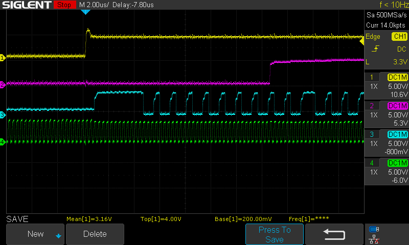
Overly complicated or not, the output seems to be in order. The boot signal (purple) goes high after the first 8 memory accesses following a reset. I'm not sure about the bumps in the rising edge of /AS (blue), but the signal is obviously good enough for the CPLD, so let's move on.
The MFP is currently the only peripheral in the system that produces its own DTACK response. The RAM and ROM are both fast enough that, until now, DTACK was tied to ground and the whole bus cycle was effectively synchronous. At low clock speeds, the MFP does actually seem to work with DTACK grounded, but since I'm having issues with it, this obviously needs to be implemented correctly.
The logic is simple: if the MFP is selected, the CPU's DTACK line should be controlled by the MFP DTACK response signal. If anything else is selected, i.e. RAM or ROM, just hold DTACK low.
In Verilog, this simplifies down to:
// Generate DTACK signal
assign DTACK = ~MFPEN & DTACK_MFP;
This logic will get more complex when other devices are added or if wait states become necessary as clock speeds increase. For now, though, it's easy to validate.

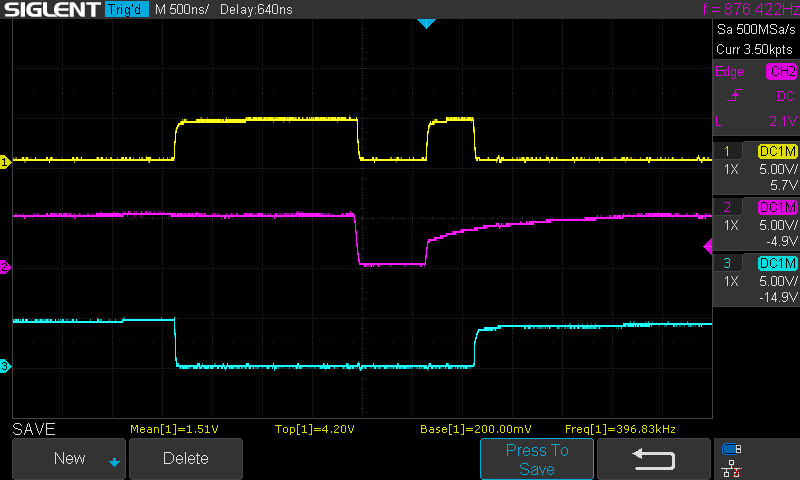
This is also looking alright. Trace 3 is the MFP chip-select line, active low. When the MFP is enabled, DTACK (trace 1) is held high until the MFP pulls it down (trace 2). When the MFP is no longer selected, DTACK goes back to ground.
When In Doubt, Slow Everything Down (and add capacitors)
In addition to properly implementing DTACK, I "reinforced" the boards with more decoupling capacitors and I replaced the clock generation on the CPLD with a dedicated 2 MHz oscillator as close to the CPU clock pin as possible. I thought it would be nice to have a high frequency oscillator feed the CPLD and then generate a system clock from that, but the generated clock signal being output by the CPLD was only hitting around 3v peak-to-peak instead of the 5v I would expect. According to the datasheet, the 68008 will recognize anything over 2.4v as high, but I didn't want to take any chances and decided to feed the CPU clock line directly with a nice clean clock signal from its own oscillator. This also means the system clock dropped from 5 MHz to 2 MHz and the "slow" clock feeding into the MFP is now running at 1 MHz (the CPLD still generates this clock).
Finally, I configured the MFP UART to run at a nice safe 9600 baud.
Success!
This seems like a lot of variables to change all at once, but in reality I tweaked a lot of these things slowly and repeatedly trying to find any improvement in reliability. I actually started with the simple stuff like slowing clock speeds and adding capacitors before I moved on to debugging my logic.
Happily, the MFP UART has been humming along all evening, transferring data and running programs with no lost bytes. I'll start to increase the baudrate and the clock rates again slowly, but at least I have a solid baseline now.
 Colin Maykish
Discussions
Become a Hackaday.io Member
Create an account to leave a comment. Already have an account? Log In.
Nice work! The 68901 can be a bit of a bear to get running (lots of evidence of that I'm my early project logs!) but it's pretty dependable once you get it going and has some nice features. Sadly we were never able to get much more than 9600 out of it (at least while keeping things stable and not using non-standard rates) and have now switched to the XR68C681 for a nice fast UART, but I still miss the old '901 for some things...
Are you sure? yes | no
Thanks! Your project logs have actually been a great resource. Nice to have a similar system for comparison when I inevitably interpret the datasheets incorrectly or hit a wall trying to debug something. I'm glad you put your thought process and enough technical details into them.
On paper, the 68901 does seem like an awesome chip, taking care of just about all the I/O in one place. It's pretty nice to program for, but it's definitely not the most forgiving IC I've ever used.
I have a handful of 68681 (older, non-C variant) chips that I need to explore at some point, but I'm not sure if those will perform much better than the 68901. I'll keep the XR68C681 in mind if I end up needing an upgrade.
Are you sure? yes | no
Great, glad to hear the logs were useful :)
I initially used the classic MC68681 too, and was able to comfortably get 115,200 BPS with it (with 3.6864MHz crystal). I only switched to the XR68C681 as it's still in production (from MaxLinear) so freed me having to source the old chips. It's (almost) totally compatible with the old MC68681 :)
Are you sure? yes | no