Probably you know the feeling: there is something in your hand, that should be junked. Like a piece of wood or a more complex thing, like a broken tool from the kitchen or from the garden shed or just even a piece of fancy looking cardboard. Suddenly, new project ideas are popping into your head: "This could be used in a maker project!"
Your environment usually does not share your awesome thoughts. (Especially, if the "environment" is your wife or mother. You must even pretend to dispose the valuable part of your future project if you want to avoid conflicts!)
This happened to me, when my kids opened the last window of the Lego advent calendars on 24th Dec and I wanted to drop the packaging to the paper trash. Then I set my eyes on this!
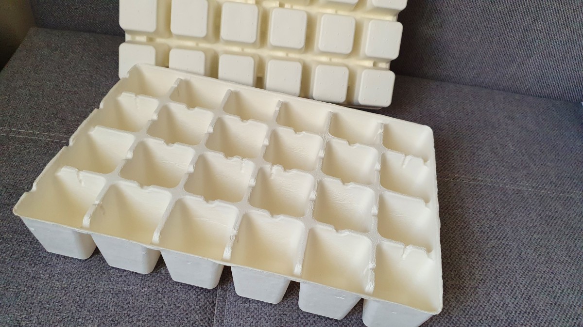
Great! I must build a LED matrix! Lets call it (yet another) LED Matrix Effect Box. This cardboard part could be the separator grid!
If you heard the tale of the stone soup, you know, that even if I have the heart of my project I still need many components around in order to bring the project alive! …some addressable RGB LEDs, a microcontroller board, wires, that's all. Ok, maybe it should provide some configurable light effects, so I need some buttons to select the mode. And an LCD display with menu and options would be great. Wait, a rotary encoder and OLED combo would be even better. Very cool! And firmware update over the air, of course, so WiFi is a must. And a mic for spectrum analyzer? Maybe later!
As I said, there is nothing extraordinary in this project. Nothing new. Connecting the HW modules together and providing a SW (https://github.com/i-kl/LedMatrixEffectBox) mainly based on great Arduino libraries. Anyway, maybe you see something that you can apply in your own project. Let's start!
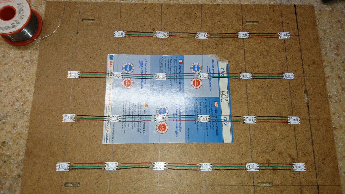
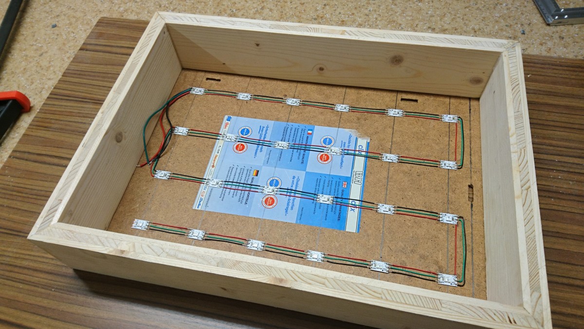
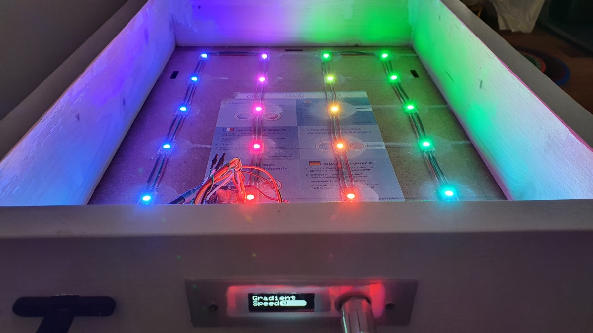
I took a piece of addressable LED strip (I used 5V WS2812 LED chips, 24 pieces). I arranged the individual LEDs in a 6x4 matrix, glued them to a sheet of wood and soldered wires between them (GND, data and +5V).
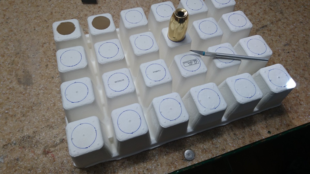
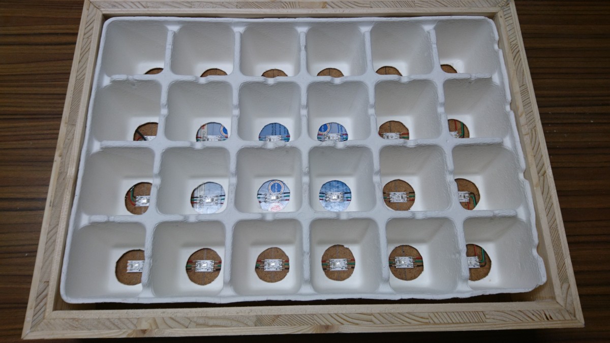
I punched/cut holes to the separator grid.
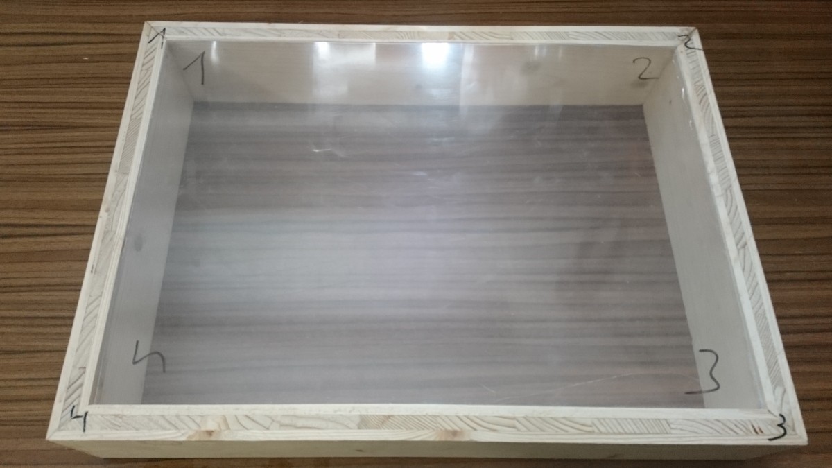
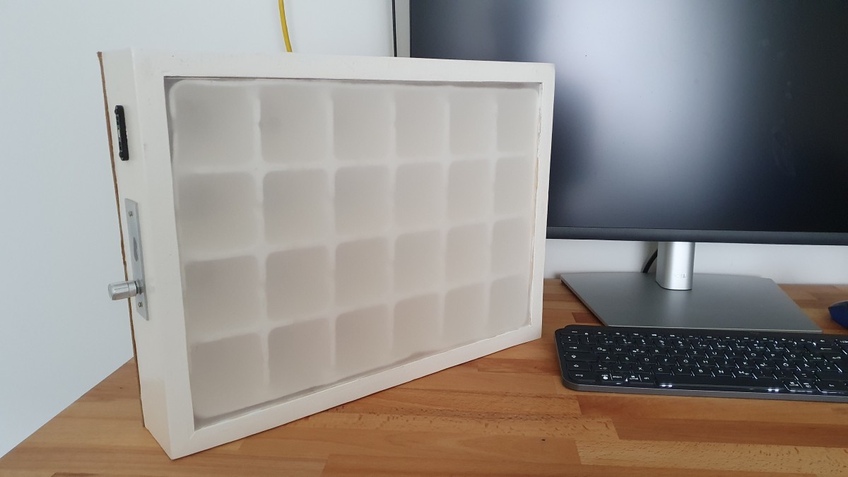
I built a wooden frame on the top of the base. The whole construction is about 415 x 300 x 75mm.
Also the chaining of the LEDs can be seen here.
Separator grid fits into the frame.
The top is covered by a sheet of plexiglass/acryl. Later I sanded it to have a diffuse effect.
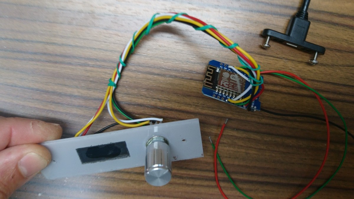
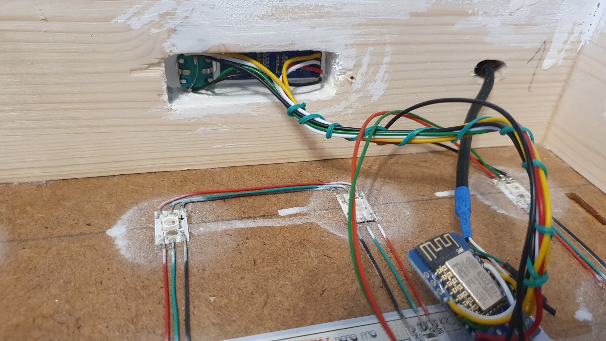
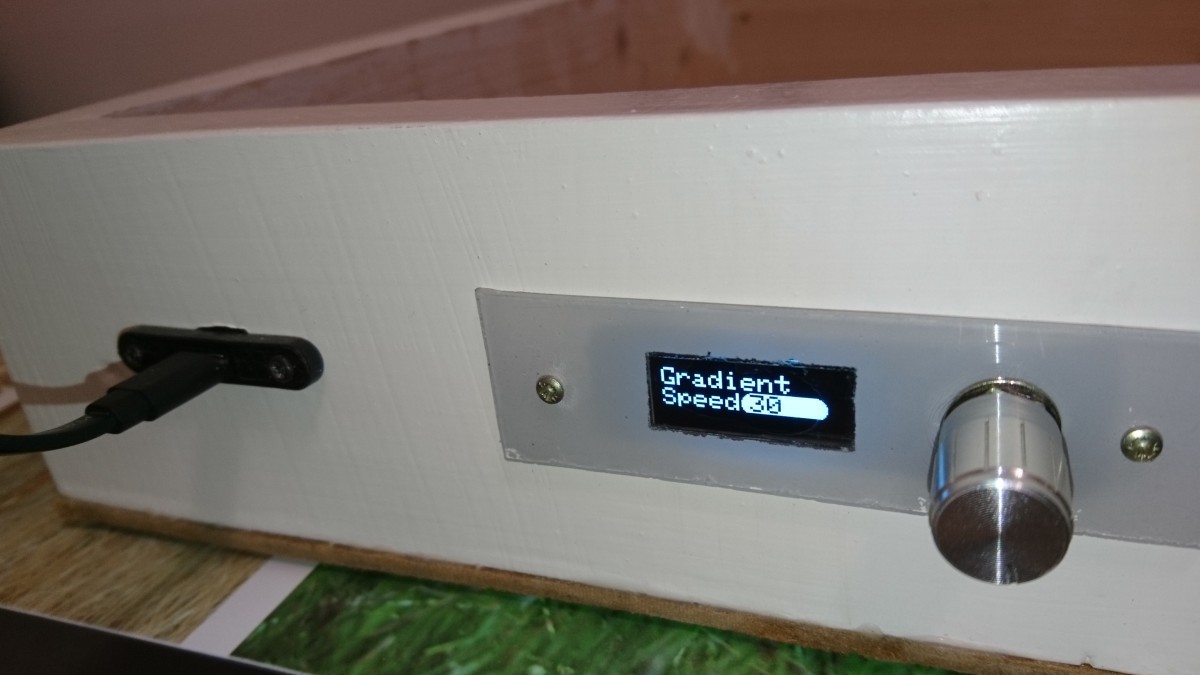
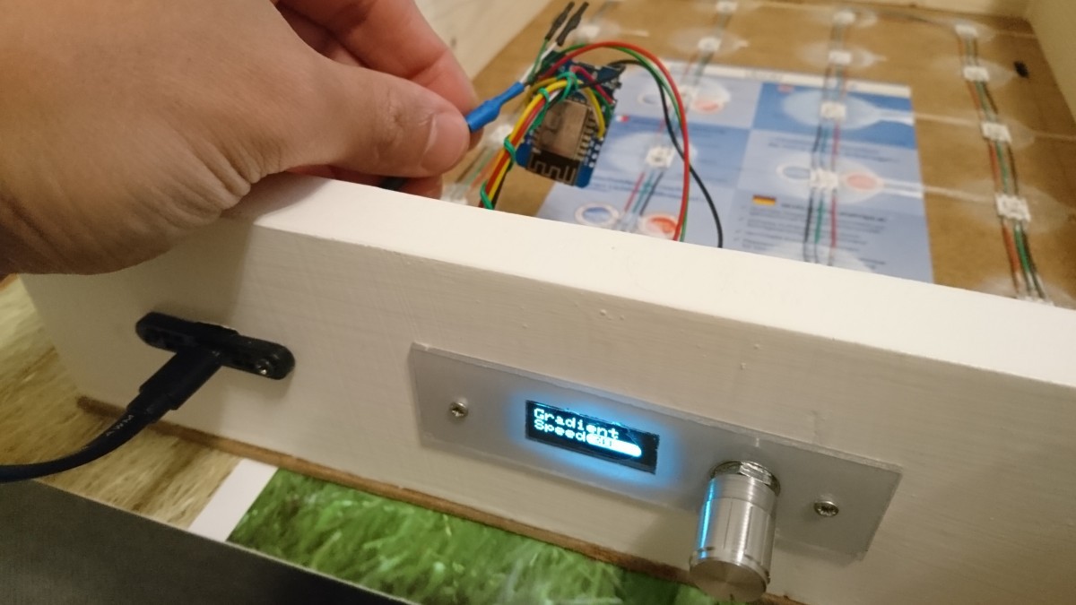
The "control panel" consists of an 0,91" OLED display module (SSD1306 compatible, resolution is 128x32) and a rotary encoder, which is wired directly to the ESP8266 WEMOS D1 (-compatible) board.
The electrical wiring is simple, I do not provide a schematic diagram here, just this pin connection list:
- D5 (GPIO14) - rotary encoder in1
- D6 (GPIO12) - rotary encoder in2
- D7 (GPIO13) - rotary encoder button
- D1 (GPIO5) - OLED 128x32 I2C SCL
- D2 (GPIO4) - OLED 128x32 I2C SDA
- D3 (GPIO0) - datain pin of the 1st WS2812 (Neopixel) LED
Of course, you can change the pin assignment as you wish, but the related SW parts needs to be adapted, too.
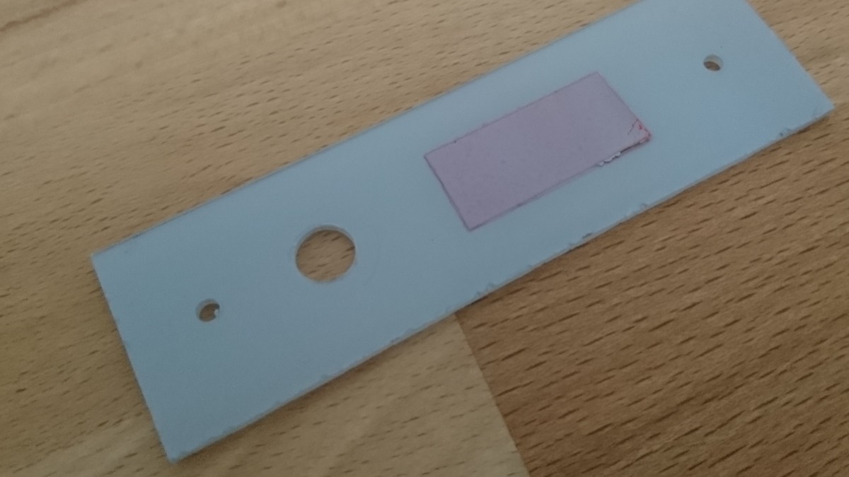
I did not want to mount the display and rotary encoder directly to the frame. Instead, I fixed them to a small plexiglass.
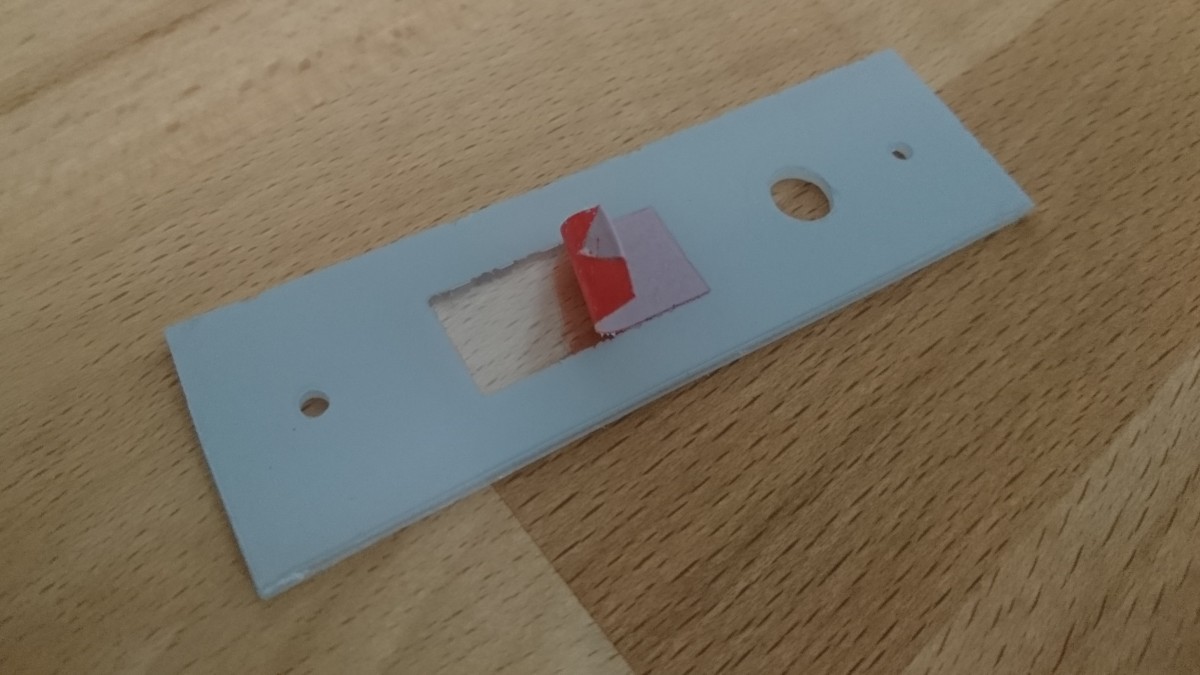
I masked the area for the display by a piece of electrical tape and painted the plexiglass part.
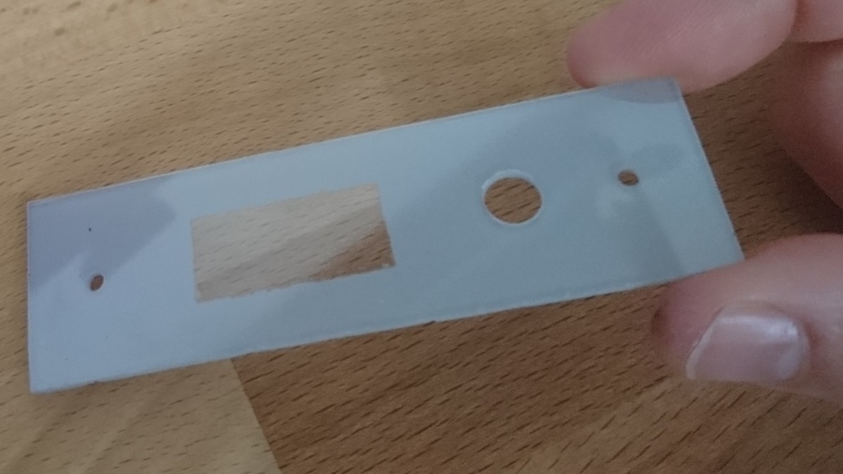
After drying, removal of the tape:
From the other side. The contour is not so sharp, but it is okay.
The OLED was glued to this. The rotary encoder was mounted by its jam-nut. Here is the whole part fixed to the frame.
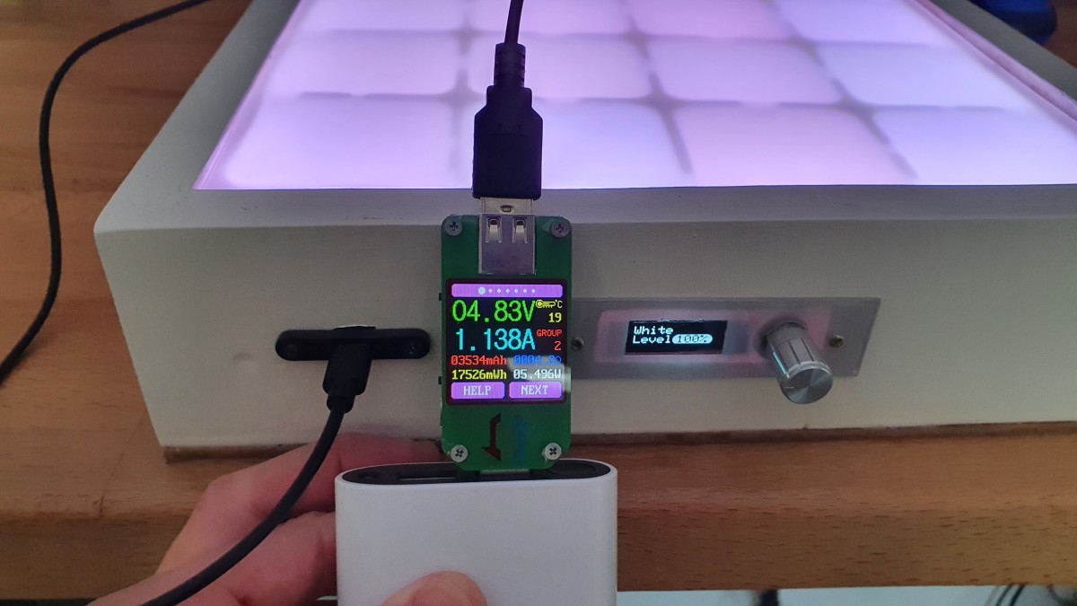
And from the front side... The box is powered via USB micro socket.
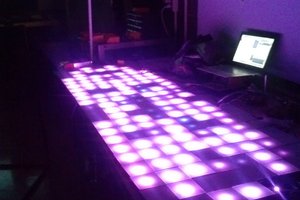
In action, however, without the separator grid yet.
Beautiful!
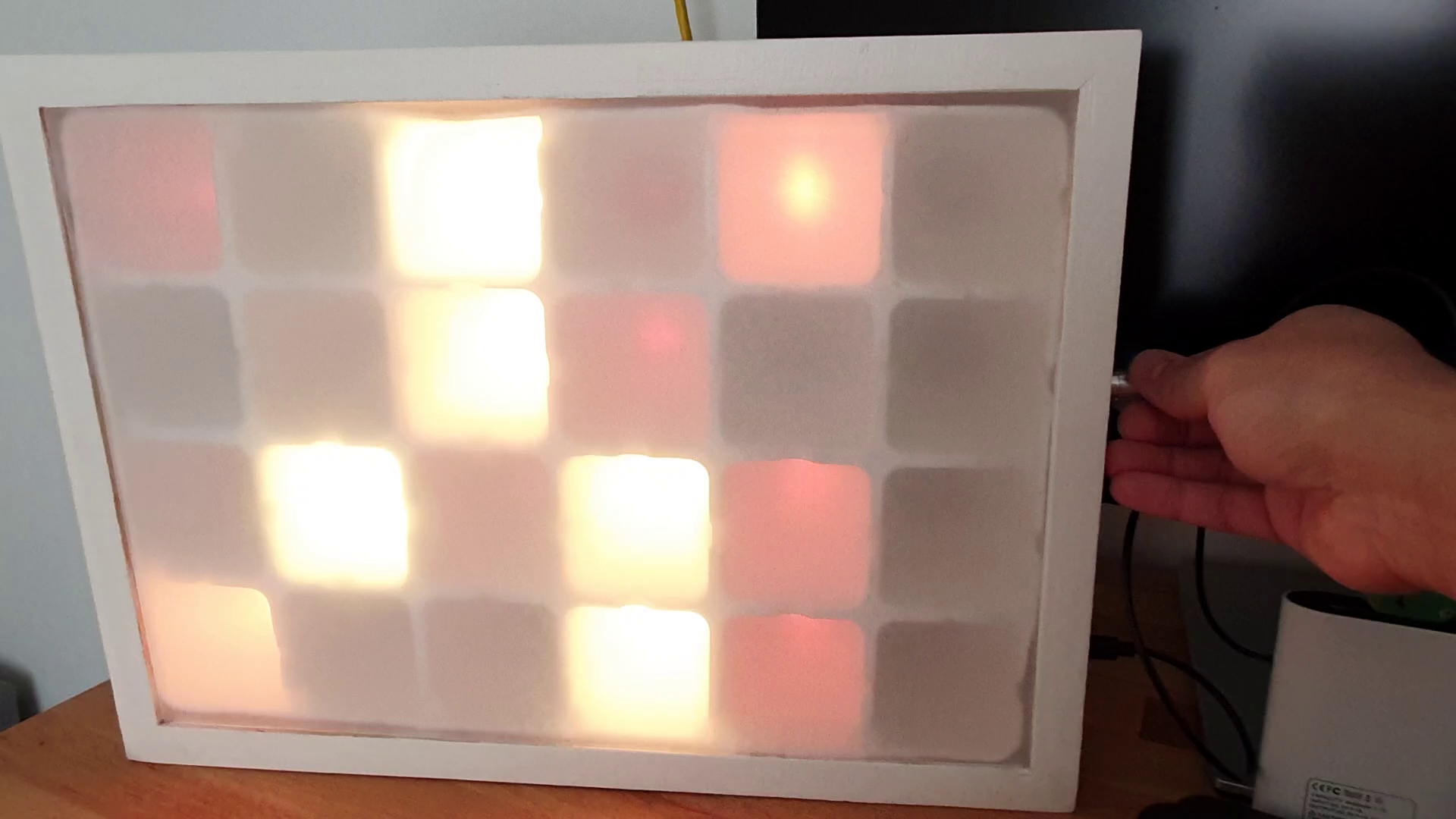
And with the separator grid. You can see the difference don't you?
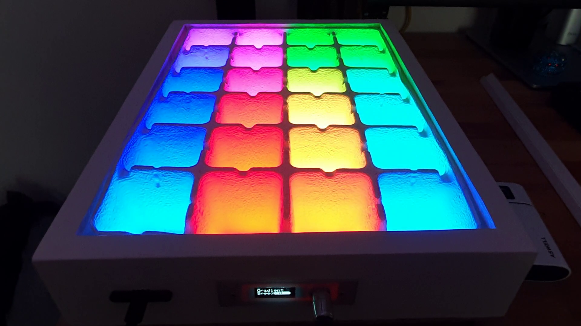
The sanded (hand sanded, grit 800) plexiglass is on the front. The box is ready.
The power consumption is max. 5V x 1400mA. This covers the power requirement of the LEDs (each R, G, B diodes at max. brightness) + ESP board + OLED display.
An example (raindrop effect)
Further effects can be seen in the related...
Read more »
 james.moran
 Sergio Ghirardelli
 Bharbour