Sagar 001
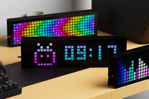
Hi guys, today we are going to discuss, interfacing of neo pixel led through NodeMCU (ESP8266-12E). Neo pixel is addressable led, we can program to display any number/name in any color using microcontroller. Neo pixel came in different smd packages, here we are using Ws2812b-5050 mini RGB.

This mini led has voltage ratings: 3.0v to 5.5volts @16mA (for each Led). Our NodeMCU has 3.3-volt regulator, to drive all the LED’s properly.
Making 7 segment display using neo pixel led:
Here, I do all the power connections in parallel and all the Data connection in series. Using the 7-segment display method, and connect all the LED’s in proper format (As in diagram).

Each of the segment has 2 LED’s and One whole panel has 14 LED’s in total. We need 4 panels to display time (2 for Hours, 2 for minutes). Two more panels can be connected to display seconds/any other values like Temperature.

Always connect Dout of first panel to Din of second.
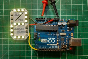
Dash connections:

To connect the hours and minutes panel, A small PCB is there in between named as Dash, contains 2 LED’s as binary digits. These 2 LED’s glow after each second.
Need of NodeMCU/ESP8266:
ESP8266 is integrated with a 32-bit Tensilica processor, standard digital peripheral interfaces.

Our Esp8266 has on board Wi-Fi support, through this we can adjust the time over internet without any RTC(real time clock) module. This will reduce the connections and make this project simple.
Supported features in code:
If you are using my code, then there are 2 extra features you may add in this 7-segment clock.
1) Temperature and humidity using tactile switch.
Add a DHT11 sensor on pin number 13 and a tactile button on pin number 12 to get the temperature values on screen in Celcius or Farenheit.

Connect the button pin 12 to 5volt using a 10k resistor and the other end to GND. Means when the button pin is pull down to GND, Display will show temperature readings. The code will also work without this Temperature sensor, so if you want to keep it simple there is no need of these connections.
2) Brightness control using LDR sensor at pin A0.

Add a LDR sensor with 10k resistor by making a resistor divider network on A0 pin, this will change the brightness accordingly. High brightness in day time, low in night. The code will also work without these sensors if you don't want adjustable brightness, it will locked on default settings.
Video: Steps involved in making this clock.
7- Segment Clock:
Now, we have 4 panels and one dash. Connect 2 panels in series in pair.

Now connect dash in between and connect NodeMCU using schematics given below:
Code:
1) First initialize the code using libraries
#include <ESP8266WiFi.h>
#include <Adafruit_NeoPixel.h>
#include <WiFiUdp.h>
#include <NTPClient.h>
#include <TimeLib.h>
#include <DHT.h>
#include <Adafruit_Sensor.h>
2) Define all pixels, I/O pins, sensor pins:
#define PIXEL_PER_SEGMENT 2 // Number of LEDs in each Segment
#define PIXEL_DIGITS 4 // Number of connected Digits
#define PIXEL_PIN 2 // GPIO Pin
#define PIXEL_DASH 1 // Binary segment
#define LDR_PIN A0 // LDR pin
#define DHT_PIN 13 // DHT Sensor pin
#define BUTTON_PIN 12 // Button pin
3) For time format connect Internet using Wi-Fi to ESP8266
WiFi.begin(ssid, password);
Serial.print("Connecting.");
while ( WiFi.status() != WL_CONNECTED )
4) Time settings on Pixel
void disp_Time() {
clearDisplay();
writeDigit(0, Hour / 10);
writeDigit(1, Hour % 10);
writeDigit(2, Minute / 10);
writeDigit(3, Minute % 10);
writeDigit(4, Second / 10);
writeDigit(5, Second % 10);
disp_Dash();
5) Color setting on panels:
if (index == 0 || index == 1 ) color = strip.Color(0, Brightness, 0);
if (index == 2 || index == 3 ) color = strip.Color(0, Brightness, 0);
if (index == 4 || index == 5 ) color = strip.Color(Brightness, 0, 0);
This is a brief about code, also the code...
Read more »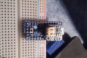
 Eric Friedrich
 Hulk
Hulk