 DIY GUY Chris
Supplies
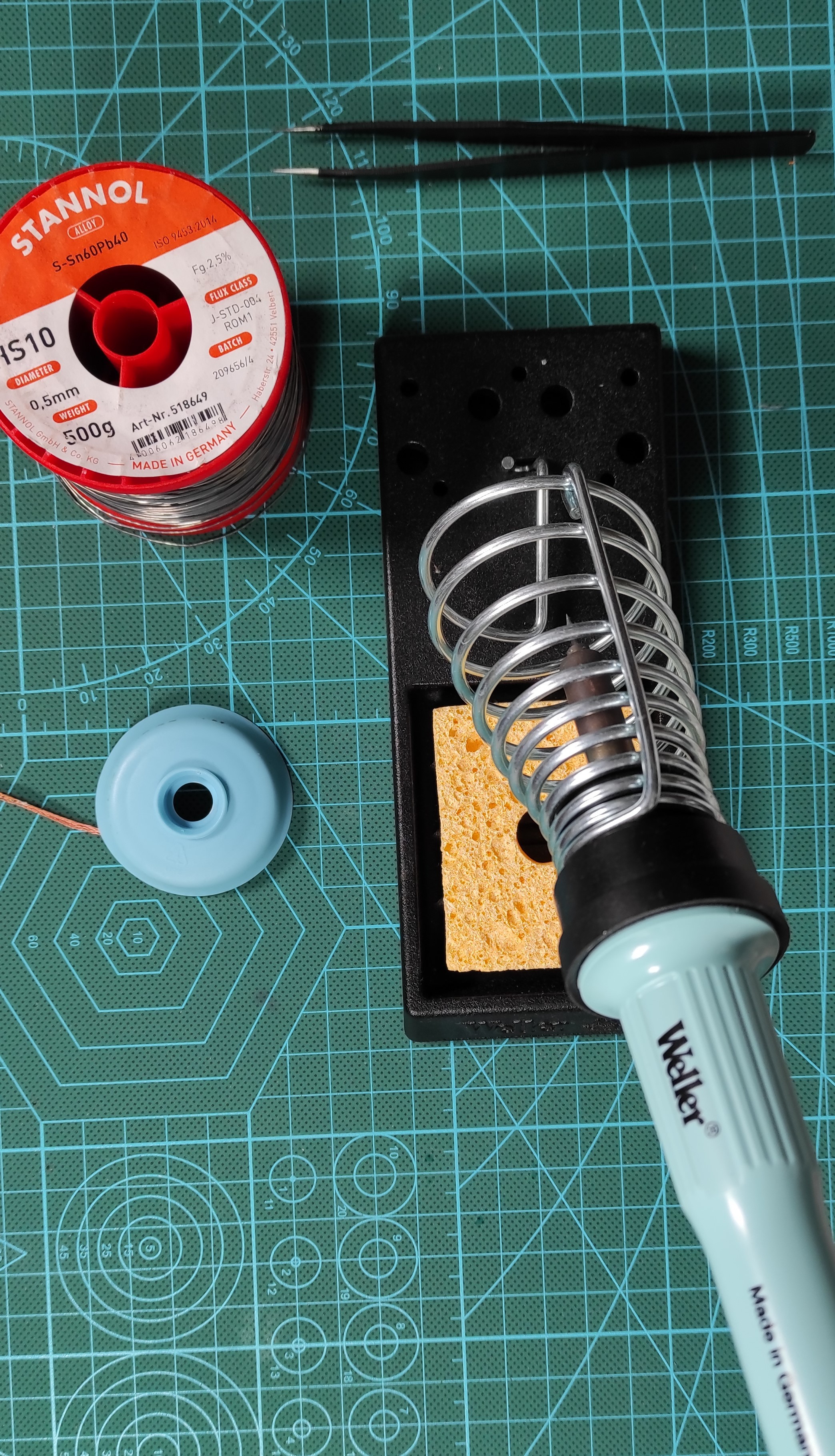
Some tools are required to perform the assembly, I used a solder iron with pointy end solder tip and small section solder core, a tweezers is also needed to handle the small electronics components.
Don't forget to use Solder wick to remove joints in case you applied extra solder core.
The Circuit Design
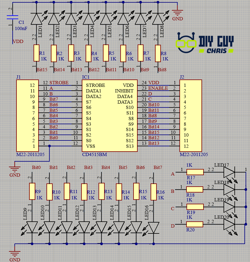
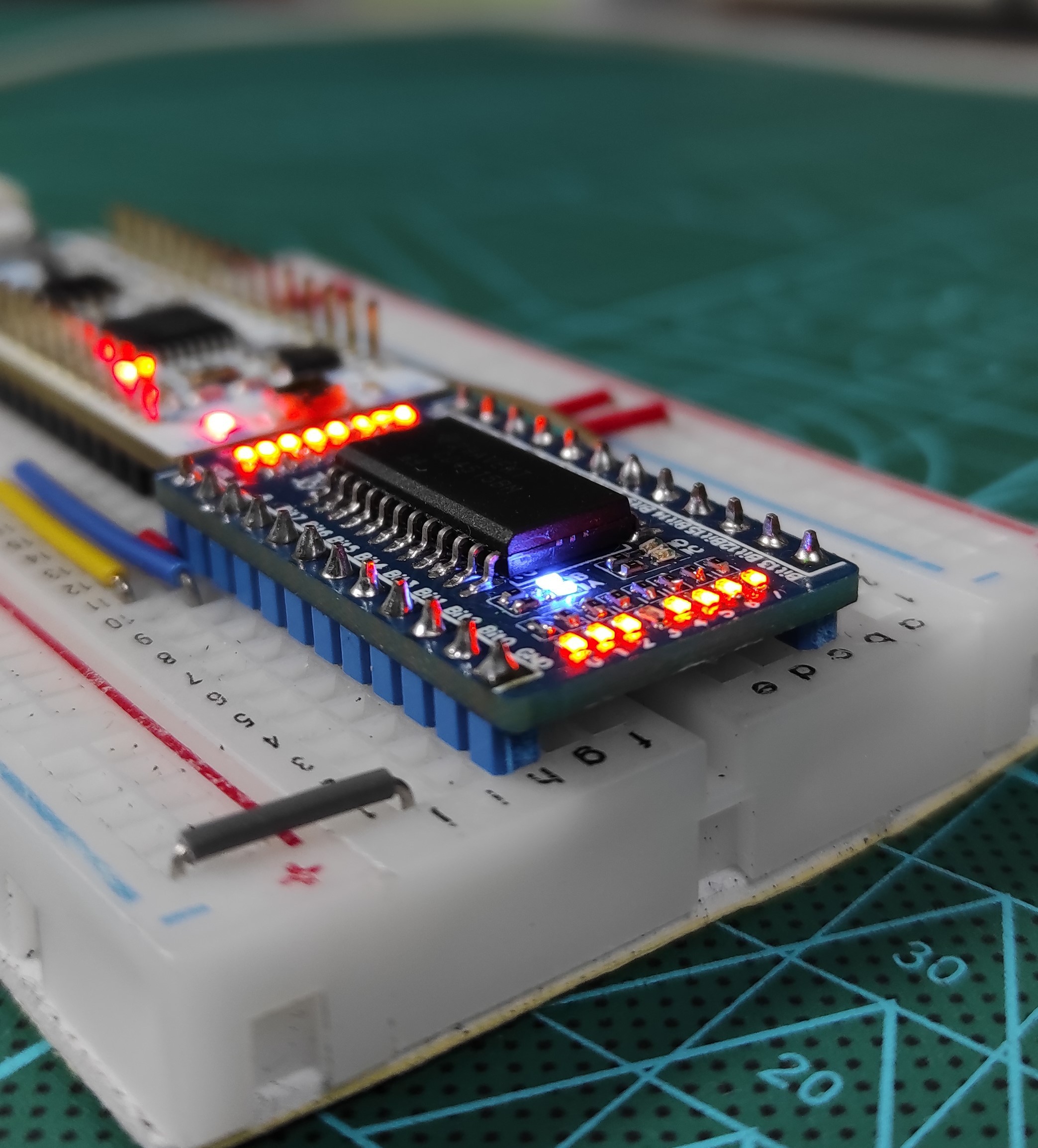
The schematic has been built around the CD4515 Decoder integrated circuit which belongs to the 16-Bits decoders category, I included some LEDs as indicators for input selection and output Bits so all in all I used 20 LEDs and 20 resistors (1KOhm), the used LEDs and resistors are 0402 package so it will not take large space in our circuit board layout.
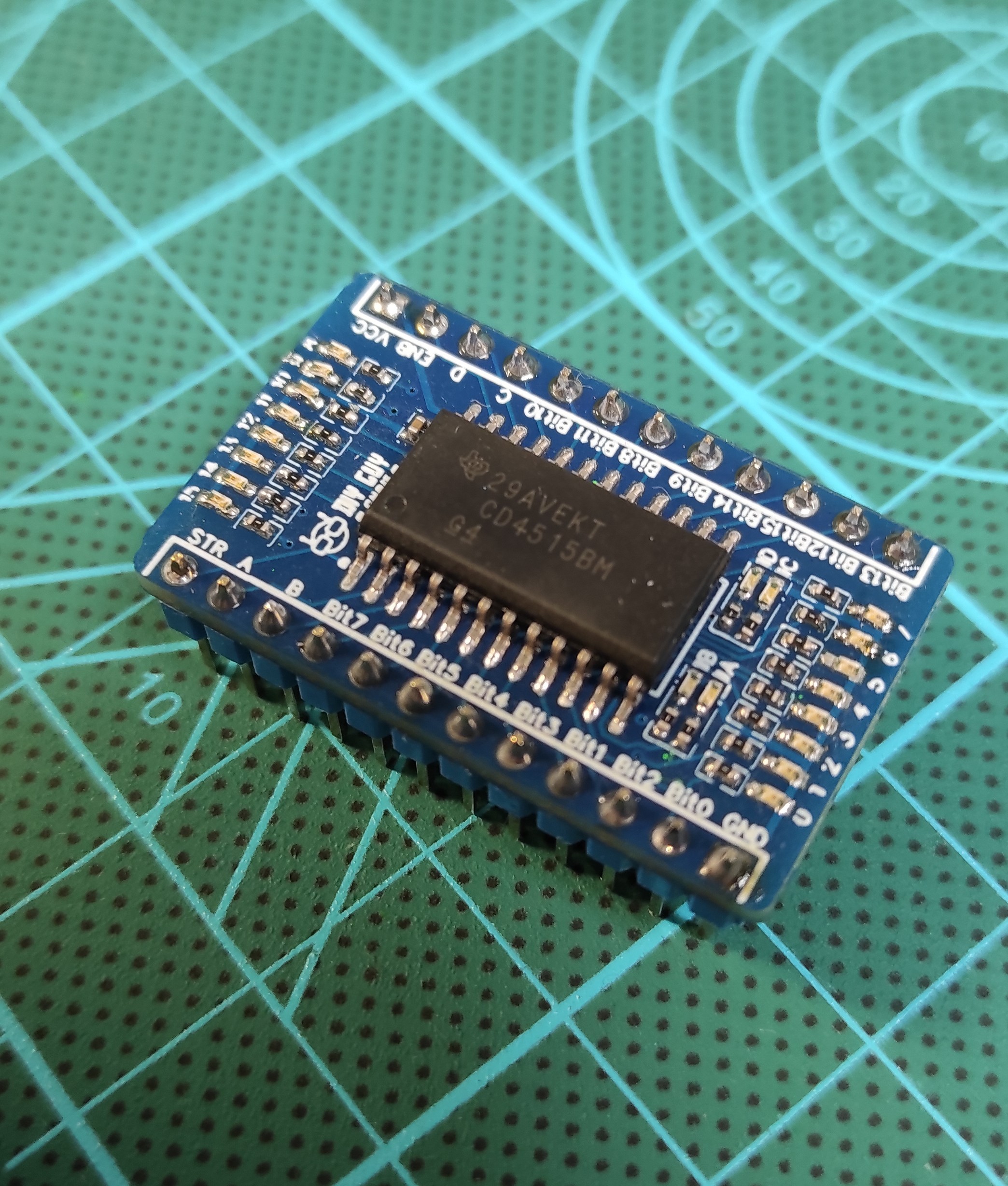
I then connected two SIL connectors (12 pin each) to the Decoder pins which will give me access to the decoder from the breadboard.
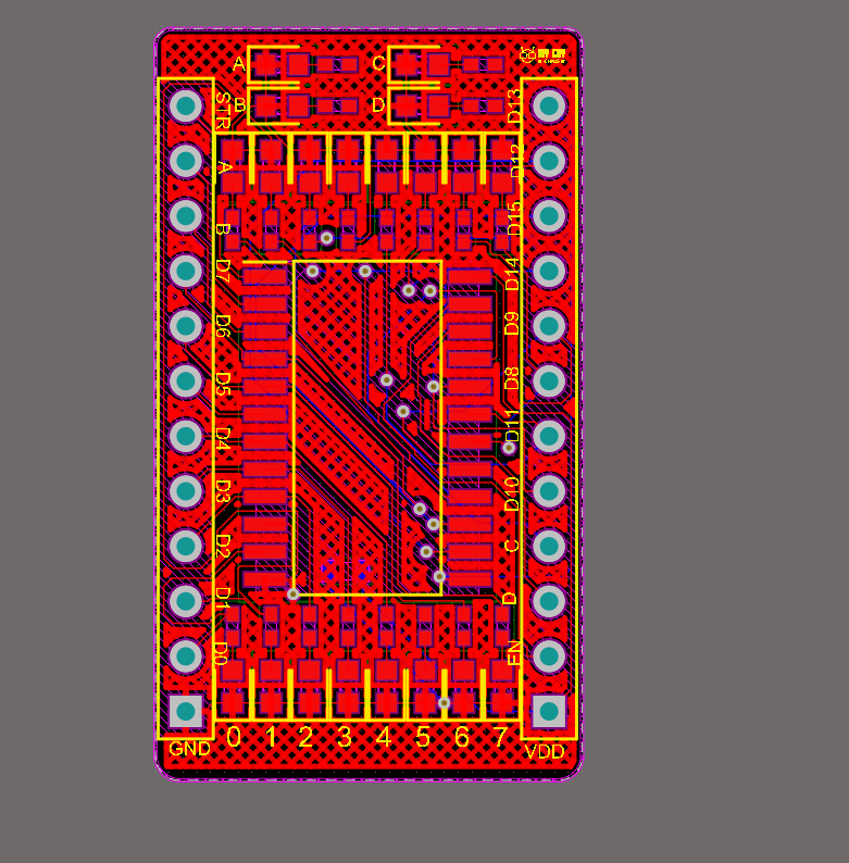
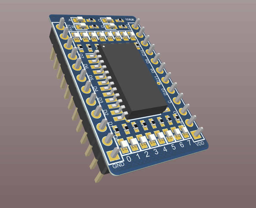
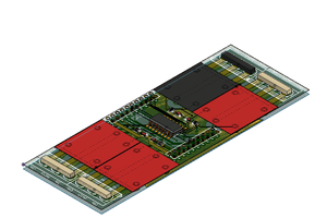
Maybe the most important part of this design is how to keep the module breadboard friendly! Simply by respecting the breadboard pin to pin spacing which is set to 1 inch it means 2.54mm, I set the board width of my module to 17.78mm equivalent to 7 inches and I placed the SIL header to the sides of the board outline with a 15.24mm spacing to make the module fits in 6 inches pins spacing, after that I dragged the decoder to the middle of the module outline then I arranged these small LEDs and Resistors inside the PCB layout.
Once you finish the design you can place your order From JLCPCB to get the PCBs.
If you want to use the same design as mine then you can download it from here
Ingrediants
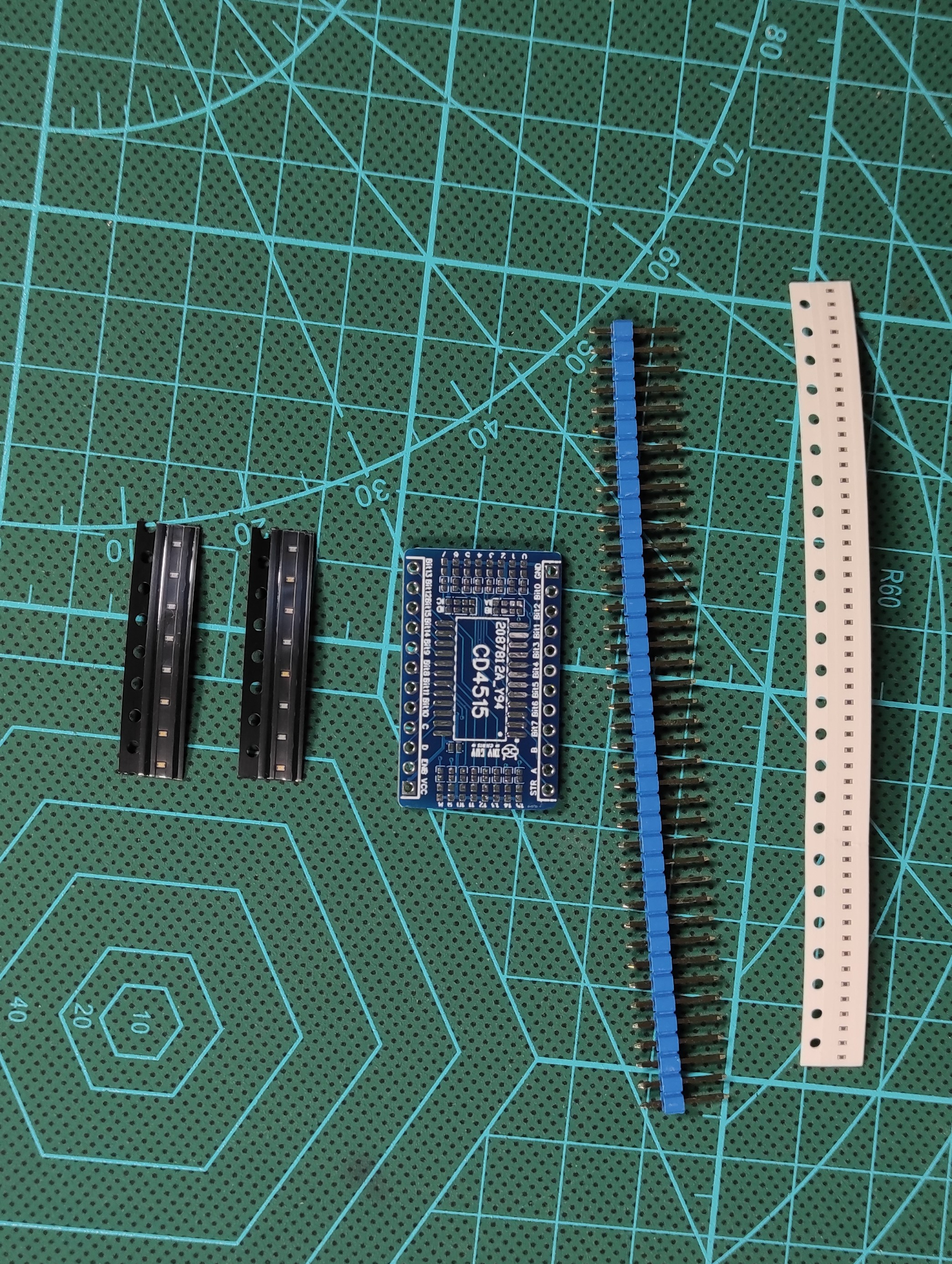
The needed electronics components are:
The PCB that we have designed
- CD4515 Decoder
- 20 LEDs (0402 Package)
- 20 Resistors (0402 Package)
- 12 Pin SIL header connector
- 100nF capacitor (0402 Package)
Assembly Result & Test
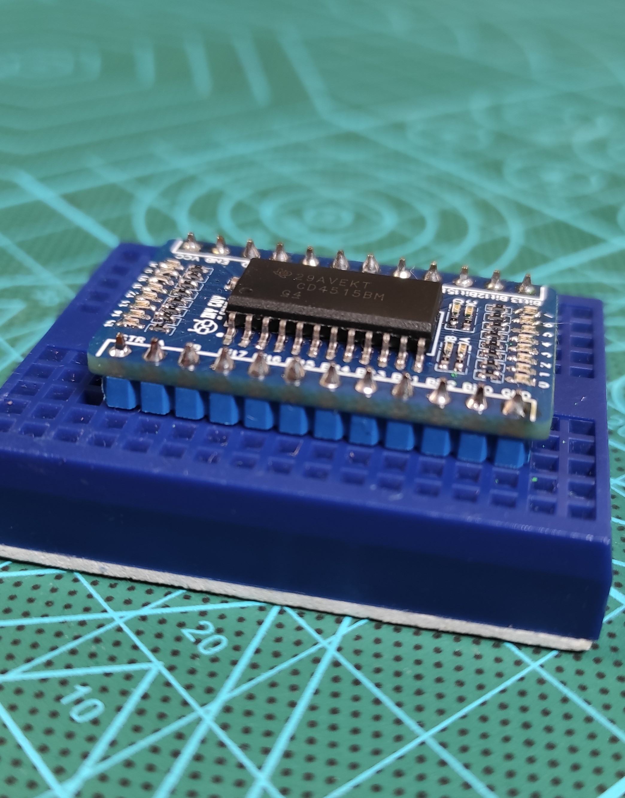
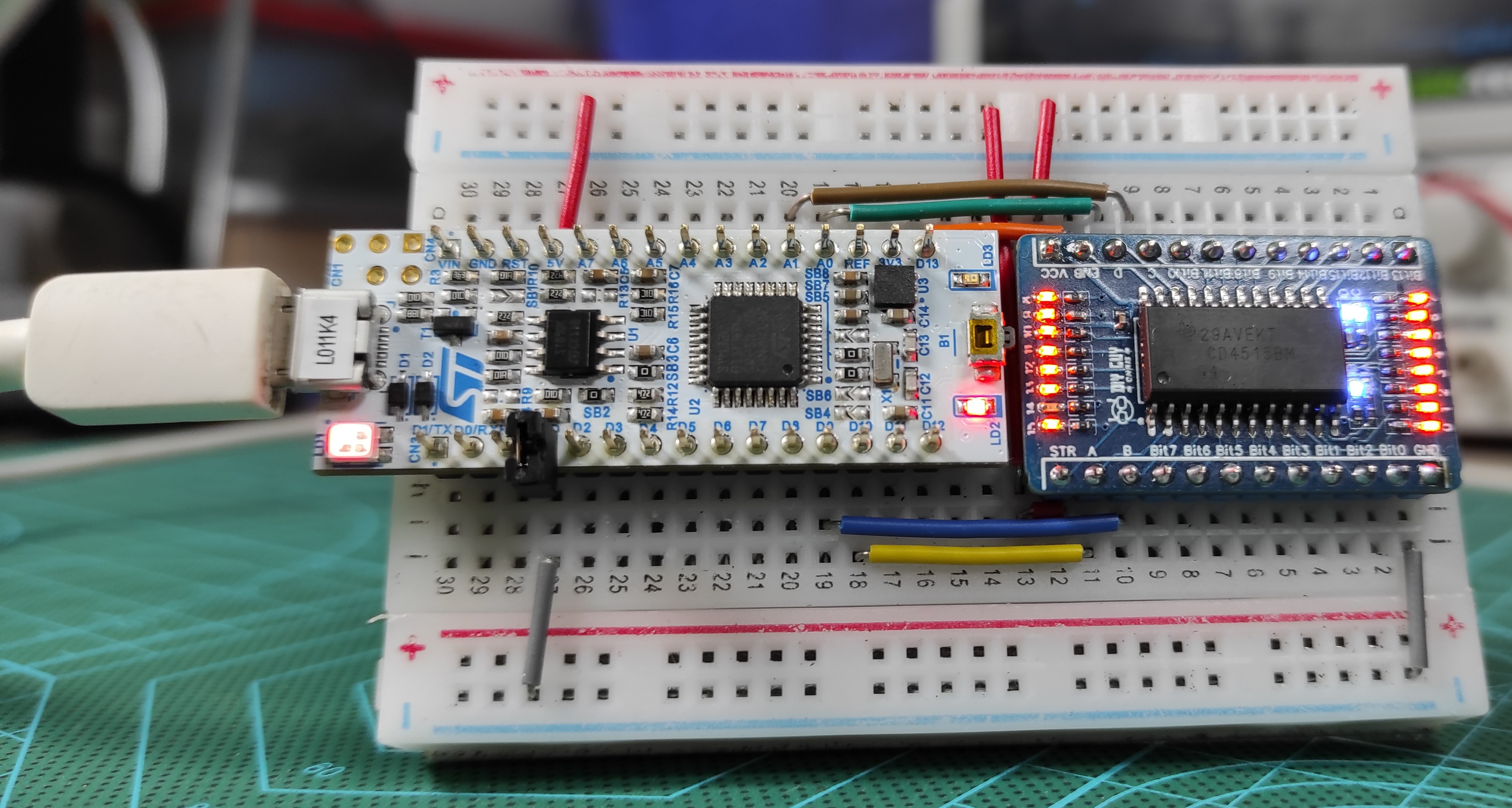
I have the module very well assembled and it fits properly to the breadboard, I attached the image of the final wirring setup where I connected my module to the Nucleo board depending on the configuration that we have made and you can see that it looks so neat, no extra wires and everything looks arranged.
Now we run the STM32CubeIDE to start the first STM project, the first step is selecting the board that we are dealing with, in my case it is the Nucleo-32 STM32L011 you don’t have to write the full board name in the search toolbar of the Selector, just write what comes after STM32 here we are dealing with the L011K4 version which is already indicated as Nucleo family.
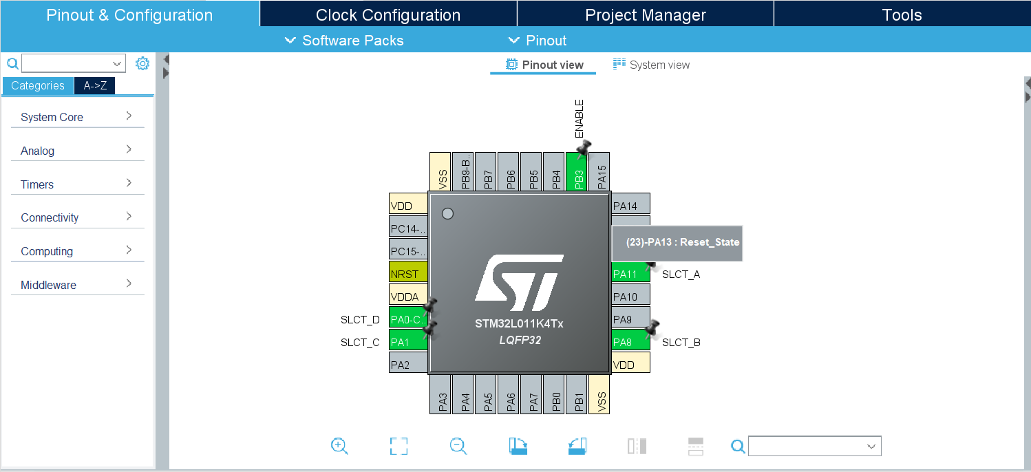
Once we have all the Packages ready, the selected MCU will show up then we do the pinout configuration from the graphical view, remember that we have 5 outputs for our module so I selected some digital outputs Labeled as SLCT_A, SLCT_B, SLCT_C, SLCT_D for selection pins and another pin that I called Enable for Inhibit pin, we generate the code for this configuration then we start dealing with the HAL library.
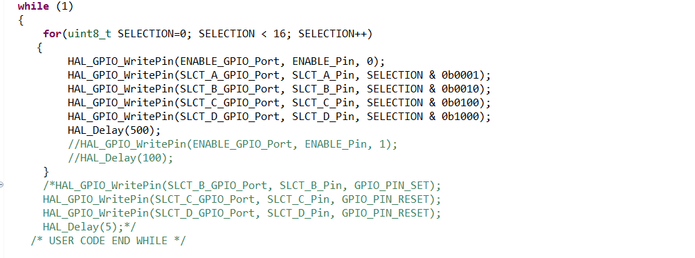
I made a for loop to select one output of the 16 pins of the decoder every half second, it means every half second, we will visualize a new combination on the selection inputs and an increment of the selected output.
The full STM project could be downloaded from here.
Thank you for reading, see you next time.
 Marek
Marek
 ElectroBoy
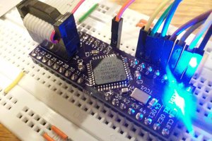
 Jon Thomasson
 Michel Racic