 Tim
TimDetails
Entry by: Tim
Technology: Bipolar/Diode logic freestyle
Size: 8 Transistors, 8 Diodes, 25 Resistors, 8 Capacitors, 7 LEDs
Architecture-, Logic- and Circuit-Optimization
What is the minimum number of discrete components required to implement the electronic dice functionality? The technology of choice is bipolar logic. Let's try to identify a systematic approach for reduction of system complexity. First, we will look at the system level, then logic level implementation and finally a circuit implementation.
System Architecture
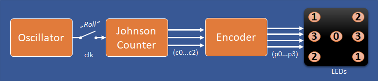
The general architecture is shown above. The oscillator generates a clock that can be activated with a push-button to roll the dice. The clock cycles a counter through six states. A really neat and effieicnt way of implementing this is with a Johnson Counter with a natural sequence length of six (see also discussion here). The counter output is encoded as three bits (c0,c1,c2) and forwarded the to encoder, which will generate the dice patterns for the LEDs. Since all possible patterns can be generated with only four groups of LEDs, the encoders has four outputs.
Johnson Counter Logic Optimization
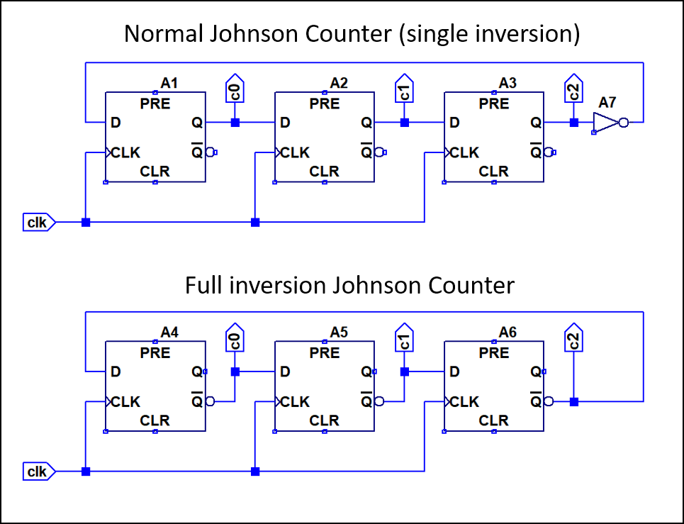
The counter consists of three clocked flipflops. Normally a johnson counter is implemented with a single inversion at the end of the chain, but for a length of three it is also possible to combine flip flops with inverting output. This can be quite neat in case we have inverting flip flops. No additional inverter is required. On logic level, this is as far is we can optimize, since the counter is basically only flipflips now.
Sequence    Normal Johnson      Fully Inverted
    1           001                   011
    2           011                   001
    3           111                   101
    4           110                   100
    5           100                   110
    6           000                   010
The output sequence of both variants is shown above. Basically the middle bit is inverted for the fully inverted version. In case our flip flops have both inverting and non-inverting output, we can of course use both the inverted and non-inverted sequence.
Encoder Logic Optimization
Now to the tricky part, encoding the counter output to the dice pattern (the pips). It appears that the proper way of doing this, would be to assign the sequence order of the counter directly to the value of the die, so that it counts upwards (1,2,3...). However, since the only purpose of the counter is to deliver a random output we can actually ignore the sequence order. This reduces the problem to encoding every counter output to a specific die pattern: we can freely choose the assignments to minimize logic.
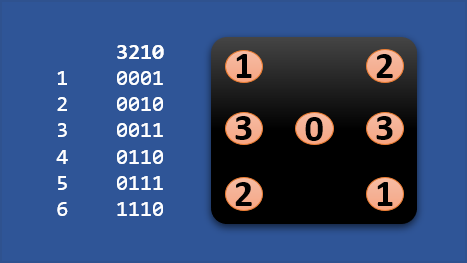
The pip group encoding is shown above. We can see that pip-groups 0 and 2 (p0,p2) basically light up half of the time, so they could be directly assigned to specific bits of the counter output. Group 1 (p1) is always on, except for one combination, which would correspond to an OR, while group 3 (p3) only lights up for one combination which would correspond to an AND.
Diode-Resistor-LED Logic
A neat way of implementing the encoding is to combine it with the LEDs. By using combinations of normal silicon diodes, LEDs and resistors it is possible to implement a wide range of logic functions. Therefore we should consider the constraints given by this implementation when optimizing the encoder logic level implementation.
Consider the generic circuit below, that shows possible combinations of diodes and LEDs.
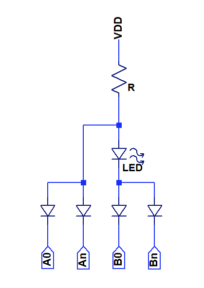
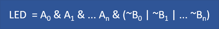
This means that the circuit can implement any logic function that can be represented by the equation above using diodes only. As an additional optimization, it is possible to omit the diode if there is only one A or B term.
Great, now we have clarified input sequence, output sequence and solution space. The professional way would now be to use some kind of logic minimization tool to indefiy an optical solution for the input output mapping, but i made good progress doing it manually, so i skipped that step.
Solution for single inversion Johnson Counter
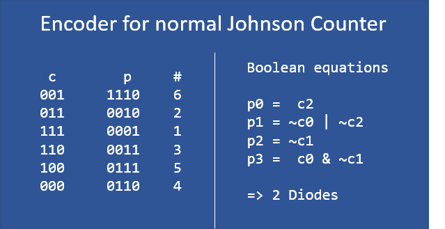
Only two diodes are needed to implement term p1, all other terms can be directly implemented by connecting LEDs to the counter outputs. Pretty neat!
Solution for fully inverted Johnson Counter
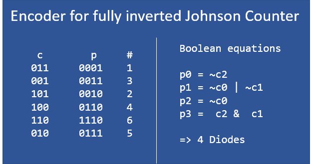
The fully inverted counter is slightly more complex to decode, requiring diodes for terms p1 and p3, 4 in total. The potential reduction in complexity of the counter is outweighted by the more complex encoder.
Circuit Implementation of the Oscillator
I played a bit with the garner oscillator suggested by Ken Yap, but could not get it to oscillate in Spice despite trying various initial conditions. It appears to me that there is a metastable non-oscillating state.
In the end I elected to go with a simple astable multivibrator as shown below.
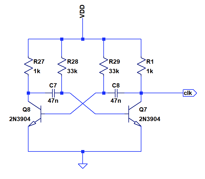
Component usage: 2 Transistors, 0 Diodes, 4 Resistors, 2 Capacitors, 0 LEDs
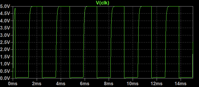
Simulation output above
Circuit Implementation of the Counter
The johnson counter consists of three clocked D-Flipflops that are implemented using a capacitor/diode pulse gate. The schematics are shown below. This is a pretty common circuit in 60ies style discrete logic but a bit temperamental when it comes to adjusting it to slew rates etc. The oscillator supplies a sharp falling edge, which works will with the implementation. The benefit of this circuit style is that it is very low in component count. A D-Flipflop implemented in static resistor-transistor-logic (think CDC6600) would require around 6 NOR gates with 13 transistors in total.
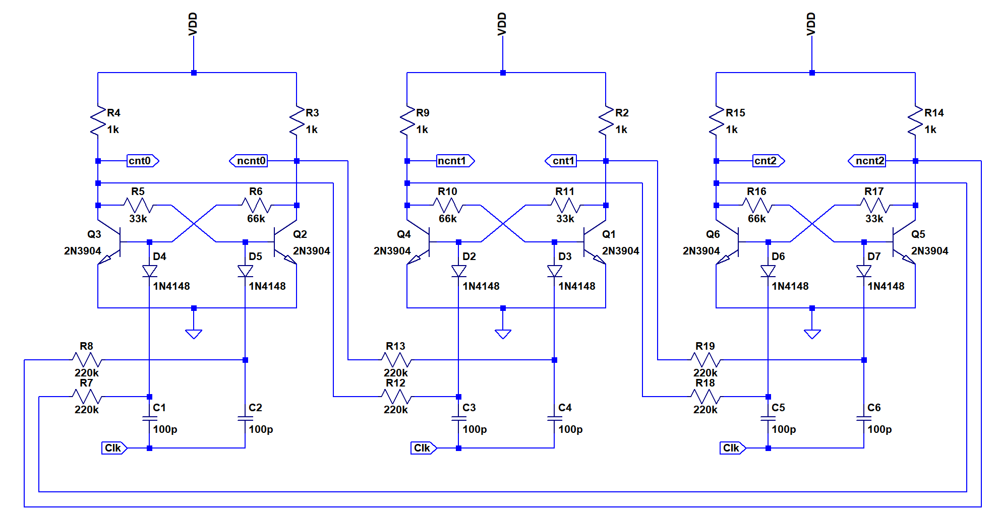
The base resistors are intentionally unbalanced to ensure that the flipflops power up to a defined state that is not equal to one of the forbidden states in the johnson counter ("101" and "010").
Component usage: 6 Transistors, 6 Diodes, 18 Resistors, 6 Capacitors, 0 LEDs
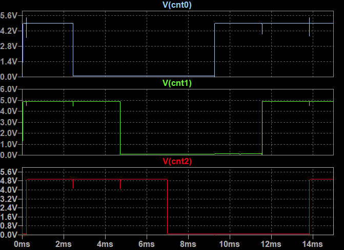
Simulation output is shown above, the sequence is "111","110","100","000","001","011"
Circuit Implementation of Encoder and LEDs
The implementation of the encoder with LEDs is shown below. As discussed before, only two diodes are needed.
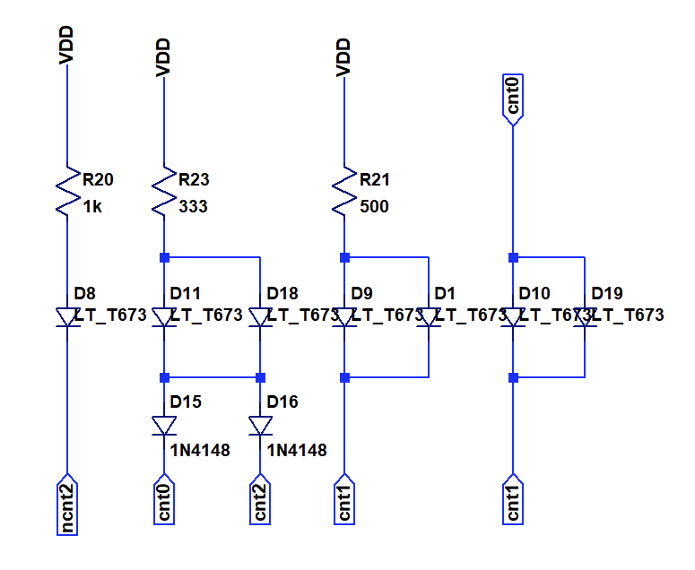
Component usage: 0 Transistors, 2 Diodes, 3 Resistors, 0 Capacitors, 7 LEDs
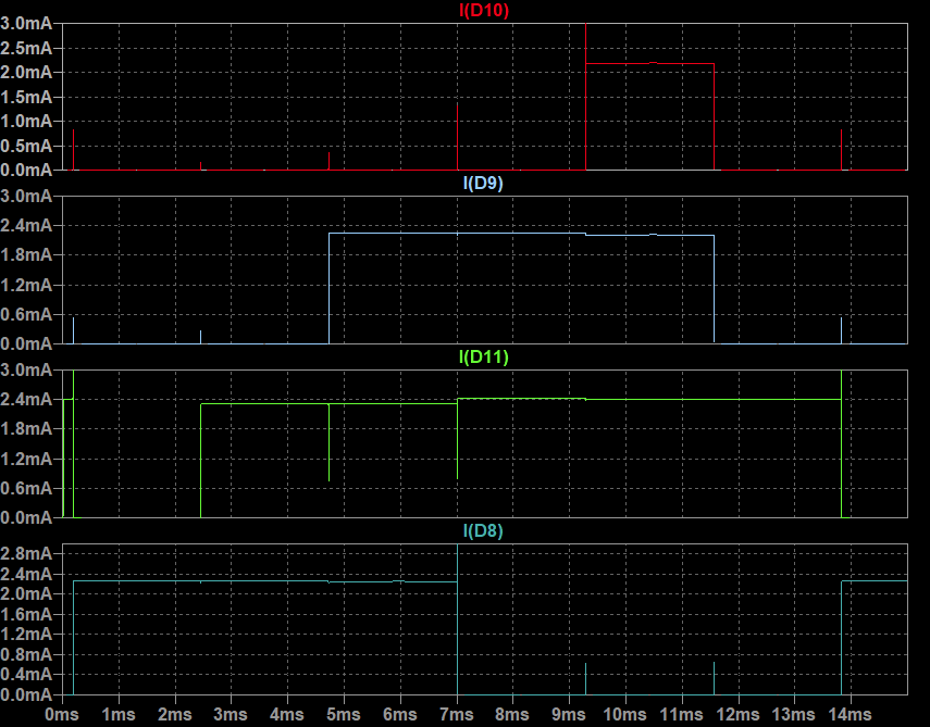
The simulation output is shown above. All six die patterns are displayed.
Design Summary
Component usage
Oscillator: 2 Transistors, 0 Diodes, 4 Resistors, 2 Capacitors, 0 LEDs
Counter: 6 Transistors, 6 Diodes, 18 Resistors, 6 Capacitors, 0 LEDs
Encoder: 0 Transistors, 2 Diodes, 3 Resistors, 0 Capacitors, 7 LEDs
Total: 8 Transistors, 8 Diodes, 25 Resistors, 8 Capacitors, 7 LEDs
Not bad at all for a fully discrete solution. Is there anything that could be taken away? On to building the hardware, or is there more?
Discussions
Become a Hackaday.io Member
Create an account to leave a comment. Already have an account? Log In.
*clap* *clap* *clap*
Now I want to see it work ;-)
how much current is it going to draw by the way ?
Are you sure? yes | no
Between 25mA and 35mA, I think the LED current is a bit high.
Not sure I am going to build this one, the PCB foir the next one is already in production though :)
Are you sure? yes | no
Well, I'd love to see this one work for real :-P
Are you sure? yes | no
Let's see, I'll finish the THT ones at first :)
Are you sure? yes | no