 Yann Guidon / YGDES
I know I know it's only a sim. For now. Because Falstad's CircuiJS is getting better at simulating relays and such. So bear (and raccoon) with me for a while, because it will be a snap to implement for real, right ? :-P
As usual I design this around the old RES-15 relays, SPDT, with the following parameters in circuitjs:
- Inductance : 28mH
- On resistance: 1m ohm
- Off resistance: 1G ohm
- On current : 50mA
- Off current: 30mA
- Coil resistance: 38 ohms
- Switching time: 3ms
The 3ms is an approximation but it gives an idea of the speed that the circuit can reach.
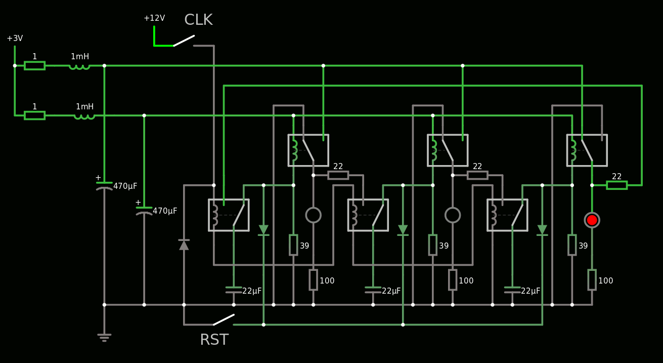
The heart of the system is a 3-stage Johnson counter, made of 3 DFF which use hysteresis for latching. Each DFF has a SPDT capacitive temporary latch to separate each stage. That makes at least 10ms overall, 100Hz max.
You can even play at home online !
The clock though is a different beast. It must be fast enough but not too fast or the JC can't follow and will end in an invalid state.
But while seeking a suitable system, I managed to find an innovative (?) Power-On-Reset circuit !
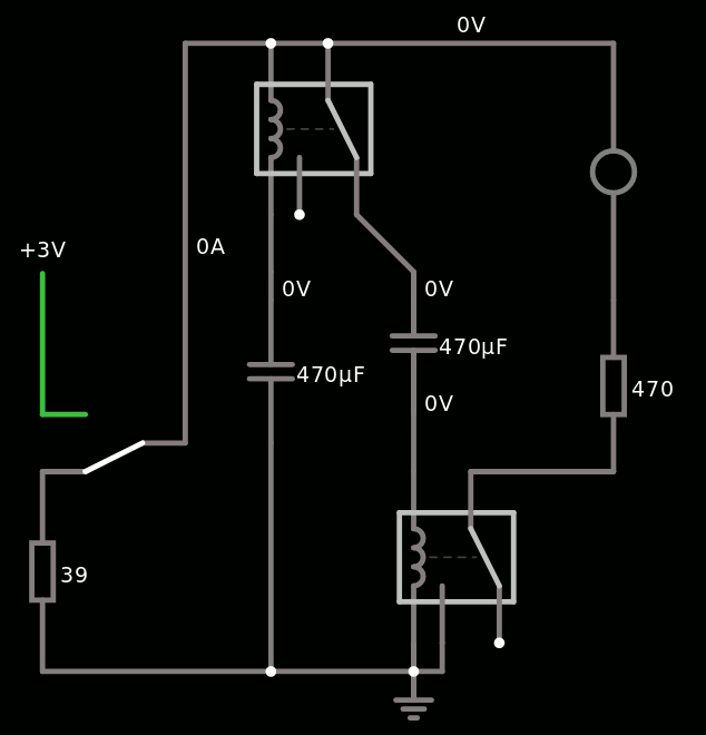
It has some interesting features :
- it waits for a first period, while the power supply's capacitors charge.
- it then send a pulse for another period
- the timing depends on the power voltage, the capacitance and the relay's resistance
- there is no shorting of the capacitors to the ground, which damages the relay's contacts
- uses only electrolytic capacitors for high storage, easier to source, since the circuit does not drive them in reverse polarity (at least significantly)
- Low quiescent current
- a proper POR simplifies the JC because there is no extra logic to design for the prevention of illegal states.
The oscillator is totally... unexpected. That's not what I wanted but it seems to work.
No, seriously, this thing is so weird. But it provides 2 outputs, one contact to 0V and one to 3V, so it can drive a buffer or something like that.
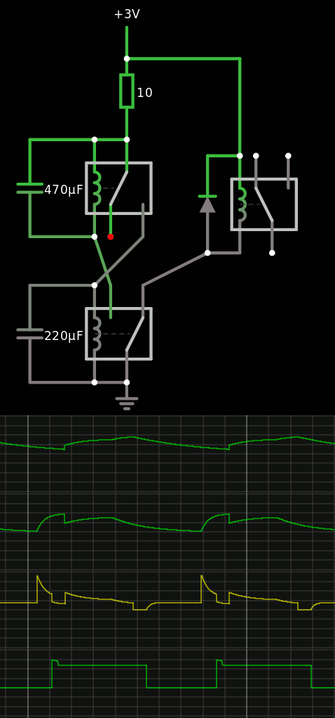
If you don't believe me, try by yourself.
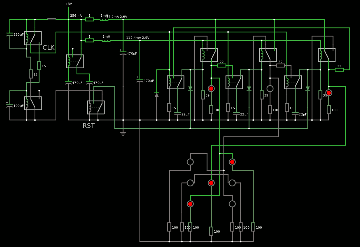
So far : 10 relays for POR, JC3 and OSC.
Together, they work nicely, I added some nice touches to reset the clock as well for example, and run on 3V 400mA:
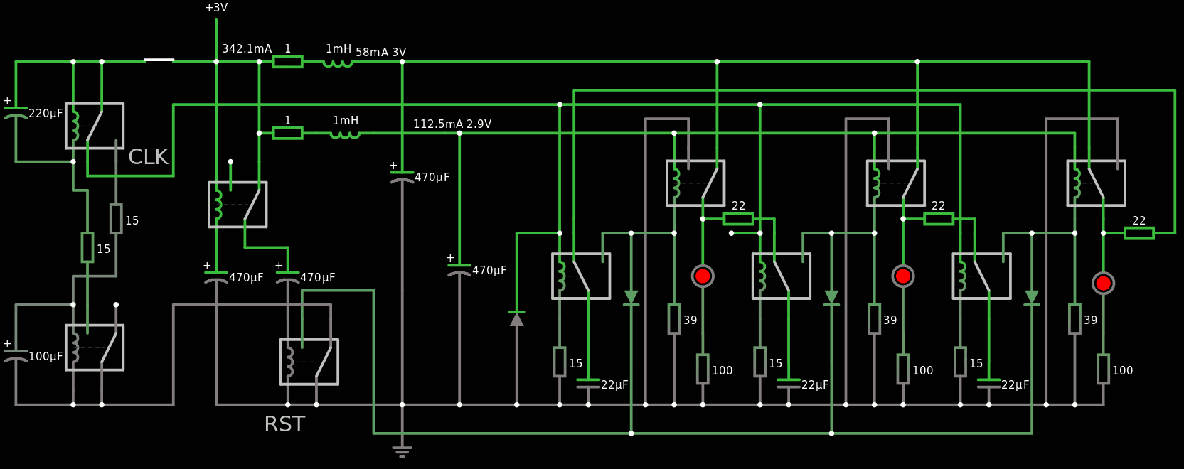
I need an efficient decoder now.
It seems that directly connecting each stage of the JC3 to a pip gives the sequence 1-3-5-4-2-0 so we're almost there!
All I need is to get rid of the 0 state and output 6 instead, right ?
I'll update the log when I progress...
Discussions
Become a Hackaday.io Member
Create an account to leave a comment. Already have an account? Log In.
>All I need is to get rid of the 0 state and output 6 instead, right ?
I think yours should be equivalent to the "normal johnson counter" solution. In that case you only need two additional diodes. (or maybe you could get away with resistors)
https://hackaday.io/project/183938-circuit-golf-electronic-dice-edition/log/203107-005-dice3904-8-minimal-transistor-based-dice
Are you sure? yes | no
I was reading it indeed :-D
You just forgot one little tiny optimisation that could save a few diodes, because you use LED and they don't light up when reverse biased, right ?
What happens when you directly connect a LED to the output (reversed or not) of a Johnson counter ? .... ;-)
Hint: https://cdn.hackaday.io/images/5270861463293298654.png
See https://hackaday.io/project/9376-yet-another-discrete-clock
Are you sure? yes | no
That's actually the case described by LED = cx & ~cy
It's a bit abstract, but at least I could make sure not to miss anything.
Are you sure? yes | no
Whoa, nice! The relays look really mesmerizing in falstad.
The number of relays is also really low. I wonder whether there is any way to remove the temporary latch?
Are you sure? yes | no
What do you mean by "temporary latch" ? The capacitor holding the charge during a half period ?
Are you sure? yes | no
Basically: Is it possible to do it with only one relay per stage?
Are you sure? yes | no
@Tim AFAIK no. One enhancement would be to use a multipole relay, like QPDT.
Are you sure? yes | no