 Tim
TimDetails
Entry by: Tim
Technology: NE555 freestyle
Size: 3 NE555, 3 Transistors, 11 Resistors, 3 Capacitors, 7 LEDs
After squeezing the last diode out of the discrete transistor implementation, let's try to optimize the circuit even further. It's time to revisit the NE555 as a main component of electronic dice, because both somehow belong together. I designed an electronic die based on NE555 logic earlier, taking a whopping 21 NE555. This was optimized to only 12 NE555 later, by introducing a Johnson counter. Now let's improve on that. This approach takes a lot of inspiration from the light dice by Dr. Cockroach.
System Architecture
Let's start with the system level again. Our common electronic die system architecture is shown below.
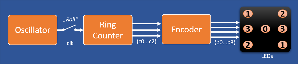
We established before, that the ring counter is the optimum counter architecture and that the encoder can be realized with almost no components by merging Encoder end LEDs. So, how can we improve further? How about merging further blocks of the system:
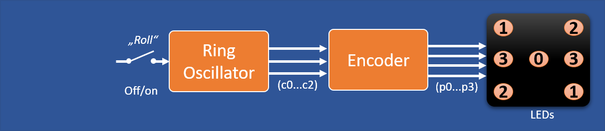
Instead of a ring counter we use a ring oscillator. The light dice uses a 7 stage ring oscillator as a counter and freezes it's contents using latches.
Ring Oscillator
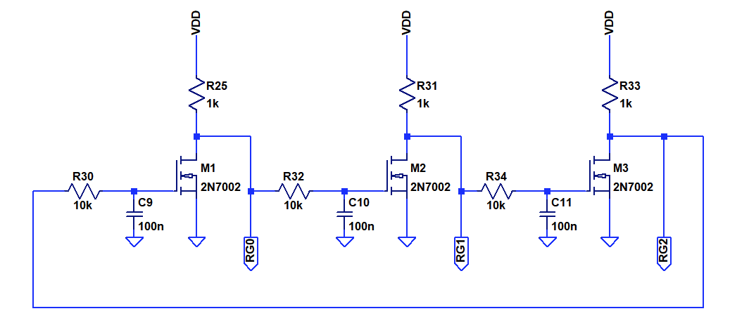
Interestingly, the behavior of a ring oscillator is very similar to that of the "fully inverted johnson counter" we looked at before. Let's take a look at a three stage ring oscillator. Each inverter stage is delayed by adding an RC element so we can observe individual states of the oscillator.
Simulation output after each inverter:
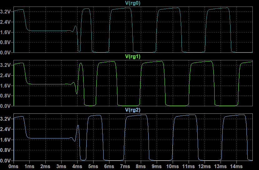
After an initial period of instability, the ring oscillator oscillates with a constant frequency. The outputs are phase shifted by 60°. Let's take a look at the detailed pattern.
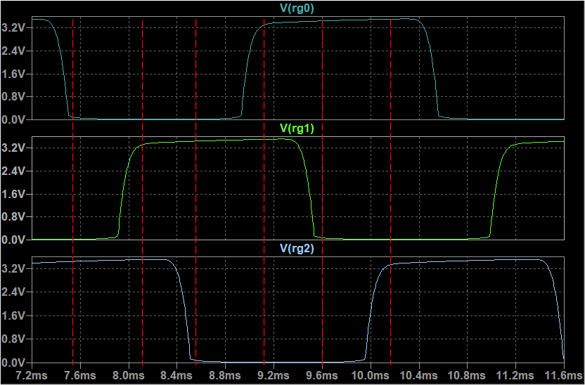
Each separate transition represents a new bit pattern. The sequence is: "001", "011", "010", "110", "100", "101" and then it repeats. So, we got a sequence with a length of six, perfect! The sequence pattern is actually the reverse of the "fully inverted johnson counter" that we discussed in the previous log.
The timing looks a bit irregular and the signal shape is not quite digital yet. Let's fix that by introducing some schmitt triggers - enter the NE555s:
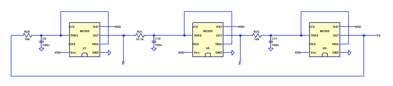
The NE555 introduces a hysteresis with equalized switching thresholds and has much more gain than the disctrete transistor inverter.
Halting the counter
Nice, now we can count through the dice sequence with very little effort. To complete the "roll" it is, however, necessary to stop the counter. One option would be to latch the output, but that would add quite some complexity.
Note that we already have a large capacitor in front of each NE555 that can holds it's charge for quite a while. This alone will be able to store the content of the counter if we disconnect the input from the output of the preceding stage.
A simple way of implementing this is by using transistors as pass gates:
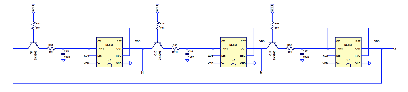
Alternatively one could simply use a multi-switch. But these are difficult to come by in this millenium and are difficult to synchronize. Here, I used PNP transistors to equalize the voltage drop on high in the NE555.
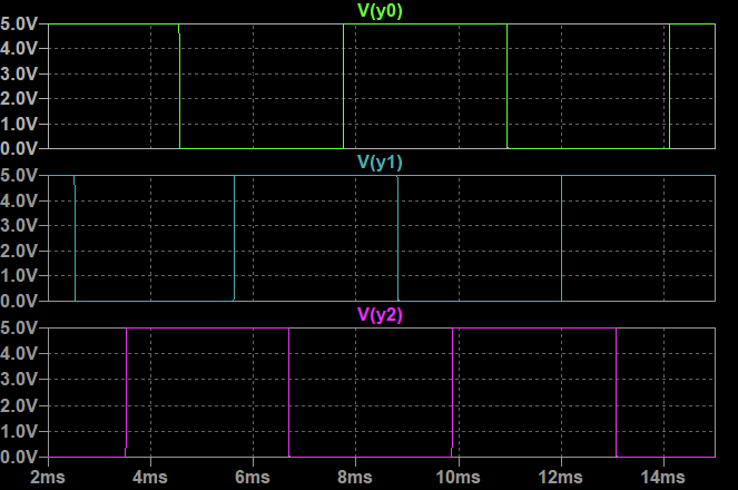
Simulation:
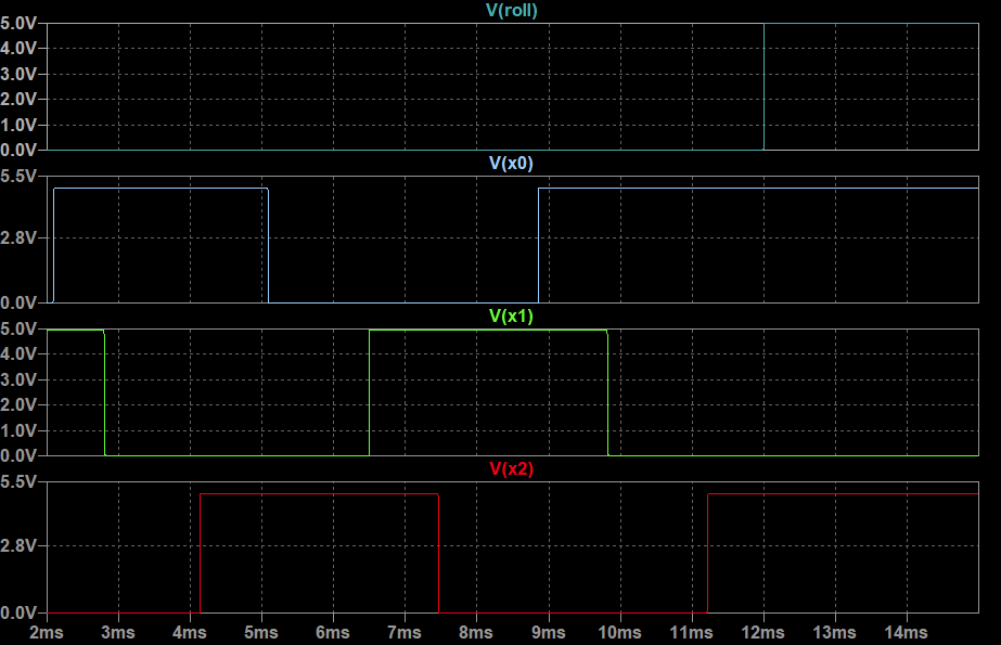
The ring oscillator is active while "Roll" is low. Once "Roll" goes high, the current state of the counter is frozen. See 12 ms mark in the simulation.
Yay! Works perfectly. An additional resistor is needed for the "Roll" button.
This concept is also known as "gated ring oscillator" and is employed in time-to-digital converters (TDC) to measure very short time intervals. For example here.
For the eletronic dice we effectively measure the time the "roll" button is held down as a source of randomness.
Component usage: 3 NE555, 3 Transistors, 7 Resistors, 3 Capacitors, 0 LEDs
Encoder and LED array circuit
The design of the encoder can basically follow the approachs for the "fully inverted johson counter" from the last log. We can, however, make use of the discharge output of the NE555 to remove the diodes. Circuit shown below. The "XD_" outputs are the open collector discharge outputs of the NE555, while the "X_" outputs correspond to the push-pull outputs.
Schematics:
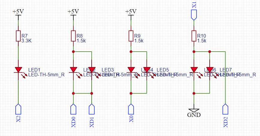
Can it get any simpler?
Component usage: 0 NE555, 0 Transistors, 4 Resistors, 0 Capacitors, 7 LEDs
Design summary
Ring Oscillator: 3 NE555, 3 Transistors, 7 Resistors, 3 Capacitors, 0 LEDs
Encoder: 0 NE555, 0 Transistors, 4 Resistors, 0 Capacitors, 7 LEDs
Total: 3 NE555, 3 Transistors, 11 Resistors, 3 Capacitors, 7 LEDs
Note that this only corresponds to 26 components in total, half of that of the discrete approach previously. In principle one could replace the 3x NE555 with 1x 74HC14 and two extra diodes. But that would keep the component count the same.
A fully transistorized version would add 3x NFET, 3x resistor and 2x diodes instead of the NE555 - still much smaller than the discrete implementation from the previous log. But due to the low slew rate of the inverters and assymetric threshold, one would also freeze transitional states which would lend an analog touch the the circuit. Schematics:
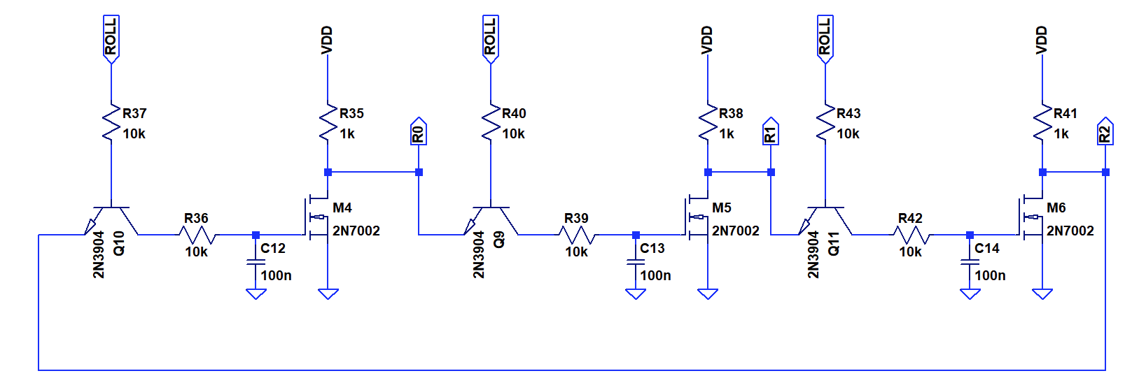
Can we still improve on that?
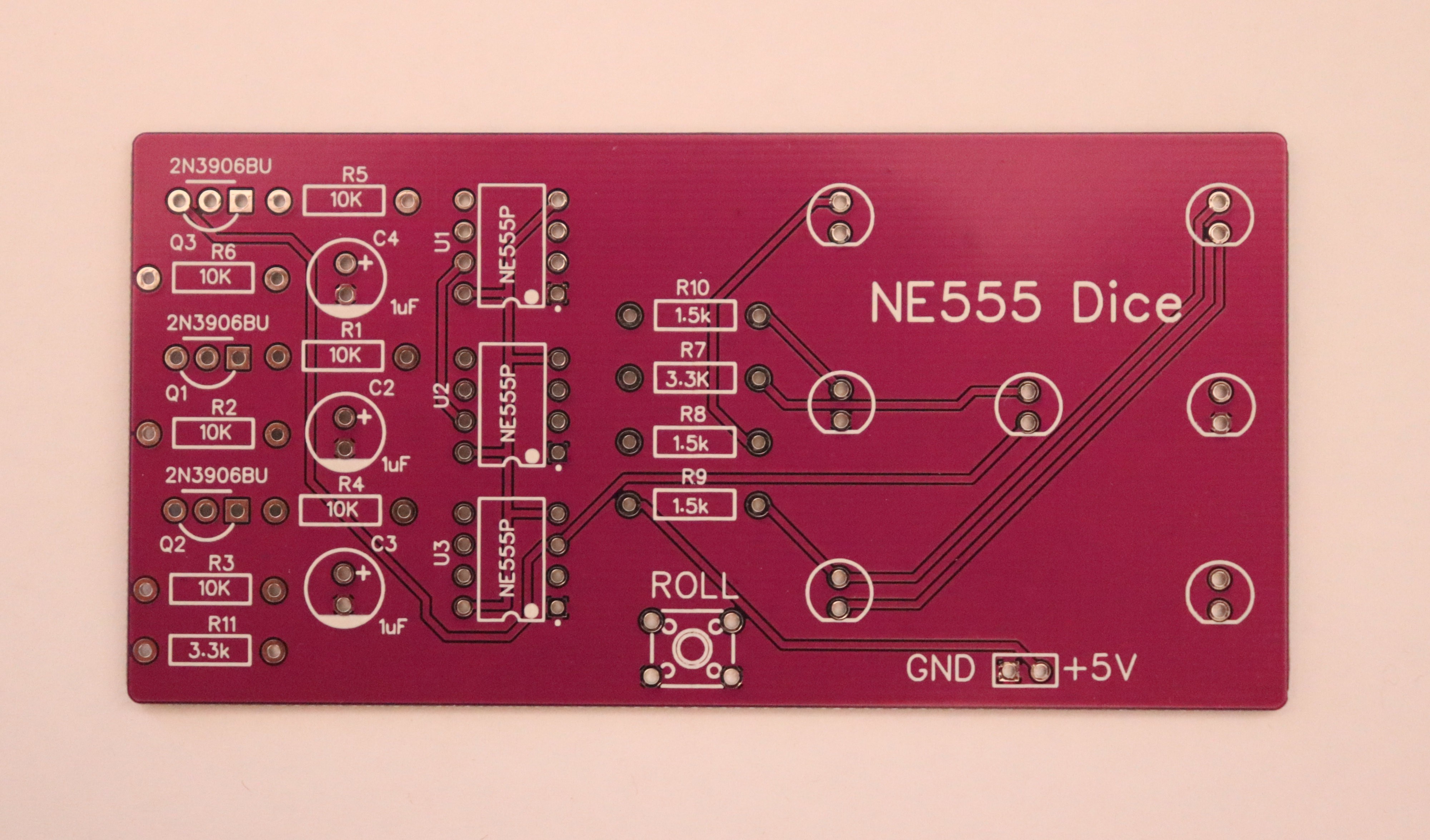
PCB Design
To honour this as a fresh approach to a 40+ years old DIY electronic design kit, I designed a through hole PCB.
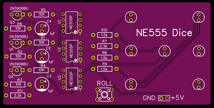
Ok, using two layers, grounds planes, and solder resist is somewhat new. I am also shocked about the bad availability and high cost of THT components today...
The PCB is being made right now and I will update with actual hardware.
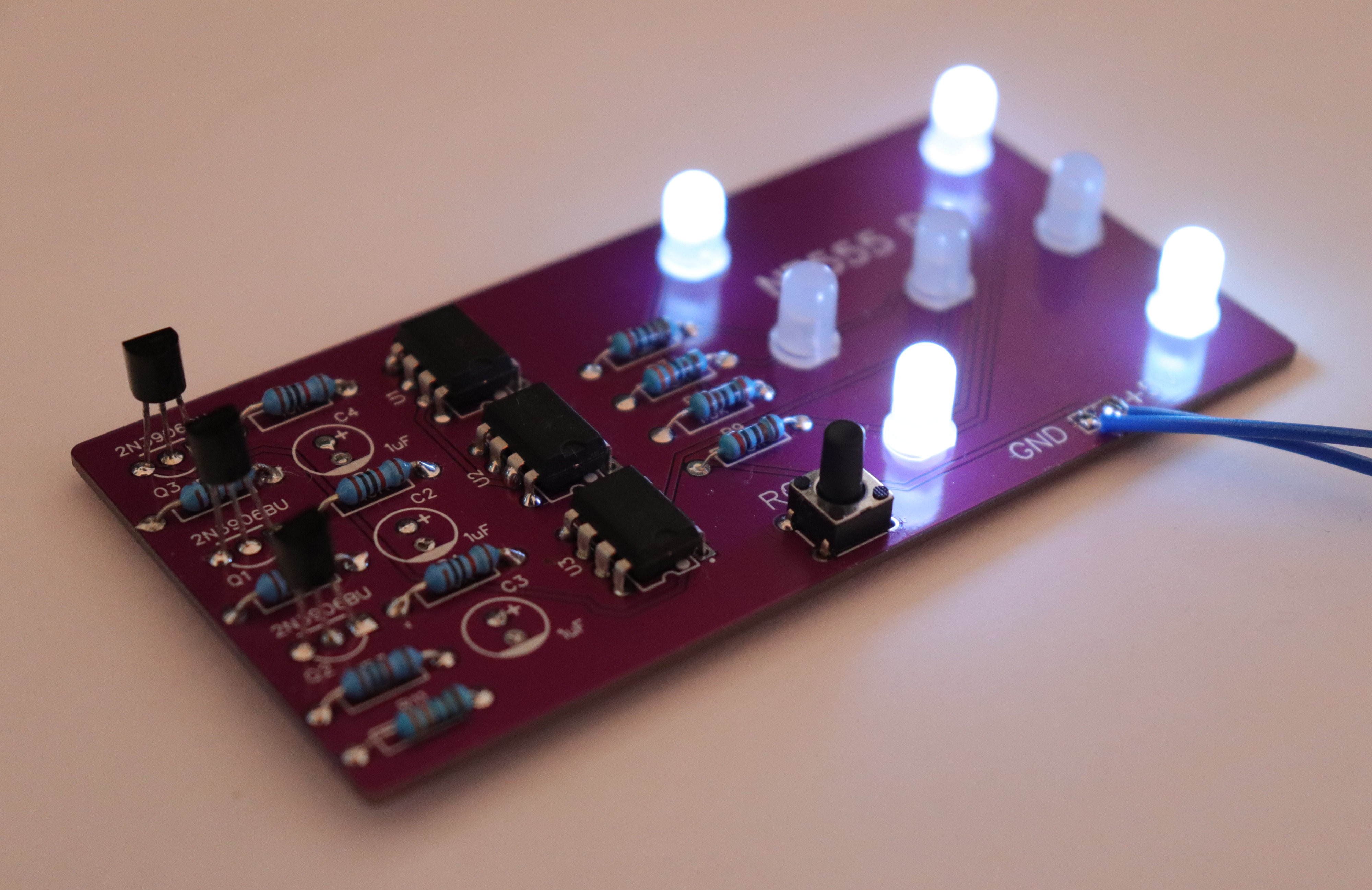
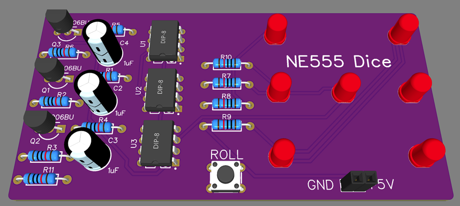
Validation in Hardware
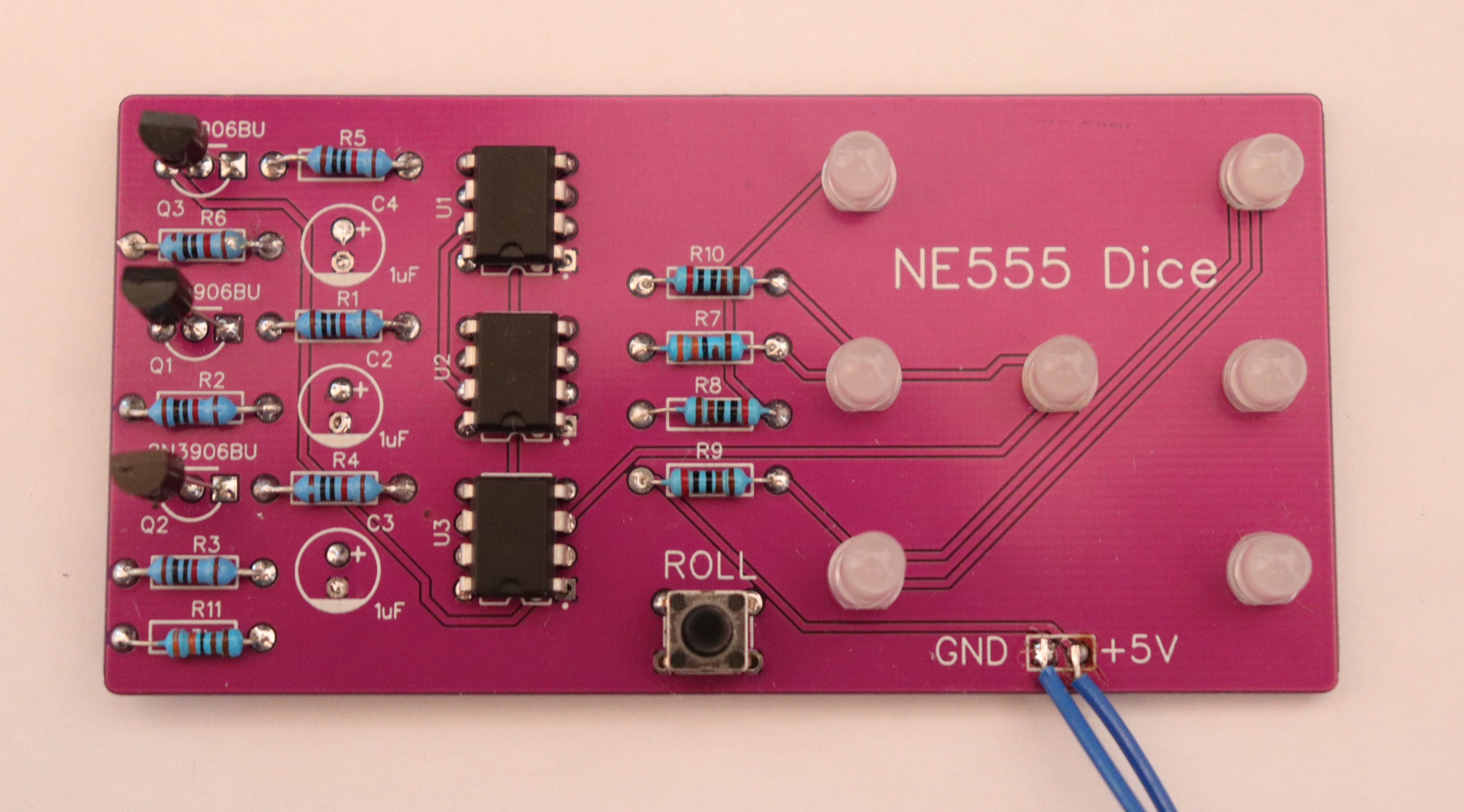
Populated PCB. Nice flashback to THT soldering. Somehow SMD is easier in the end, isn't it? I was also surprised about the large size of everything. It didn't looks that large in the design tool :) I could not find fitting electrolytic capacitors, so instead there are SMD caps on the rear side of the board. I have ordered some for a more faithful build, though.
Discussions
Become a Hackaday.io Member
Create an account to leave a comment. Already have an account? Log In.
Would it be possible to get a picture of the back of the PCB?
Are you sure? yes | no
https://hackaday.com/2022/12/11/ne555-based-electronic-dice/
Old news is new again, @Tim
Are you sure? yes | no
The NE555 is fifty years old now, a few month don't make a change. :)
Are you sure? yes | no
The numbering is off by one... should be #006 :D
Are you sure? yes | no
Where? I don't see anything ;-)
Are you sure? yes | no
Oh, I must be too tired and I read incorrectly ;-)
Are you sure? yes | no