 Coders Cafe
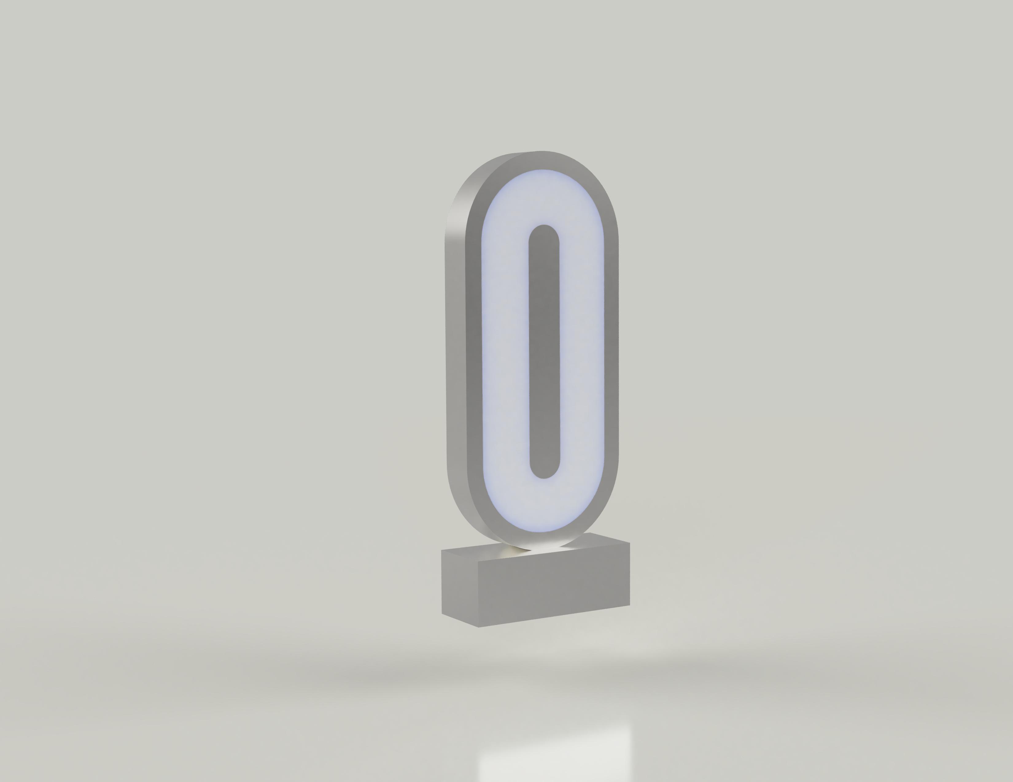
Meet Loopie, a minimalistic, enticing RGB LED lamp that can easily fit everywhere in your living space. The unique mystic shape of this lamp will make you lose all sense of time. In this video, we will be guiding you through the steps explaining how to build it on your own. It's very cheap and easy to replicate. Are you interested in doing it yourself? Let's get building.
Design
In this project, we've chosen a rounded rectangle shape that is not commonly used for LED lamps. But Why?
Let's learn some psychology. There are many interesting facts to consider when working with different shapes in design. It takes less cognitive brainpower to see rounded rectangles than it does to register sharp-cornered ones. This means it takes the visual senses more time to register the points of a rectangle than with an ellipse of the same size. It seems that a shape with sharp corners interrupts thought by forcing the brain to pause at each point until they complete the circuit.
The first and foremost meaning of rounded shape is eternity since they have no beginning or end. The circle has a long association with the sun and Earth as well as other cosmic objects while the ellipse is similar to the whole universe. That’s why round shapes may give the feeling of magic and mystery. In addition, unlike the shapes, rounded shapes don’t have angles so it makes them softer and milder.
As a result, by choosing this rounded rectangle shape, Loopie can provide an eternal, magical, and pleasant feel to the viewers.
Electronic Components
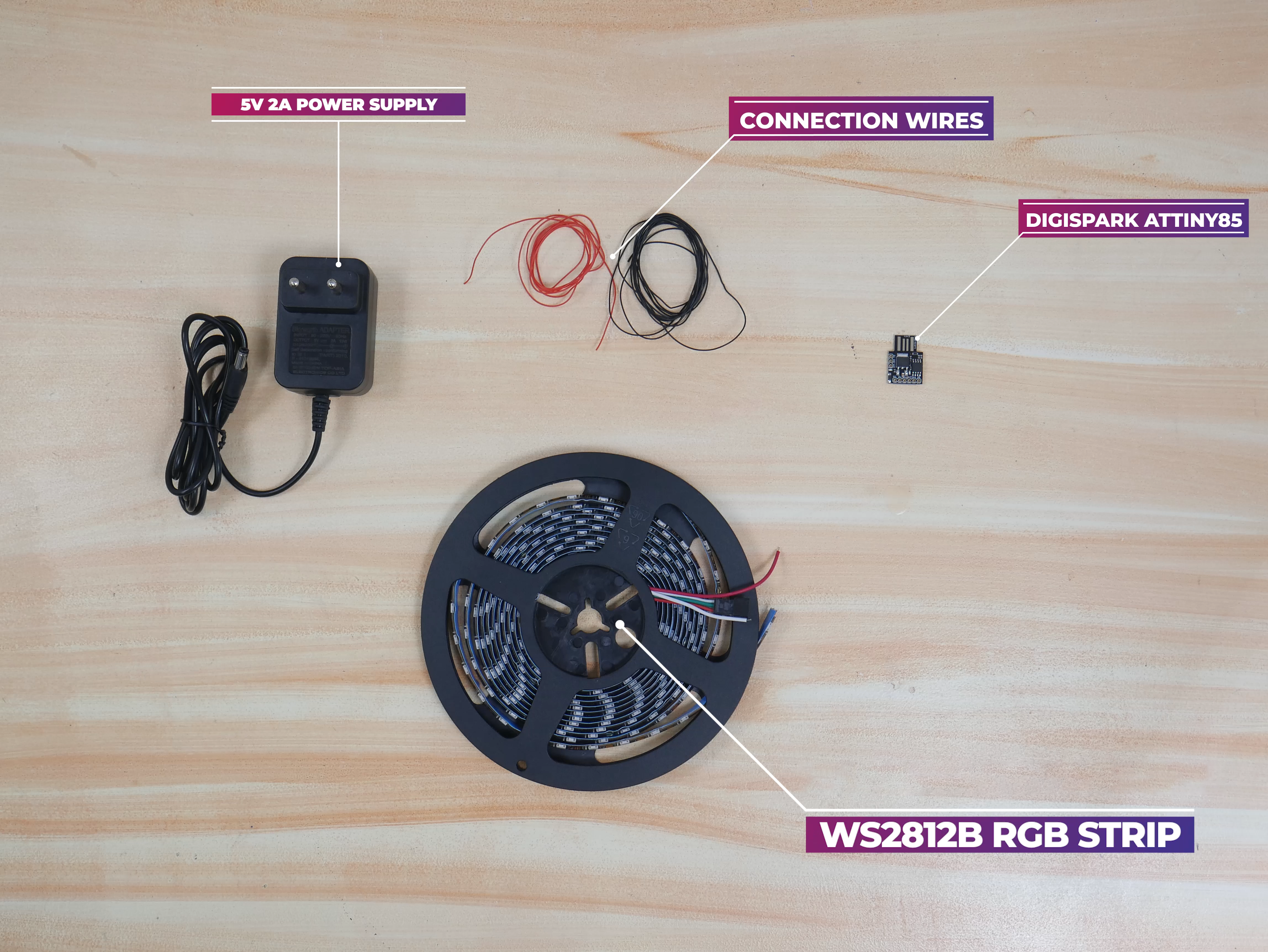
These are the major electronic components required for this project. Arduino is too big or too much for this project, so here we are going with the Digispark Attiny85 as the MCU. It is similar to the Arduino line mostly in regarding the programming way, it is cheaper, smaller, and quite powerful. It is an MCU based on ATtiny85.
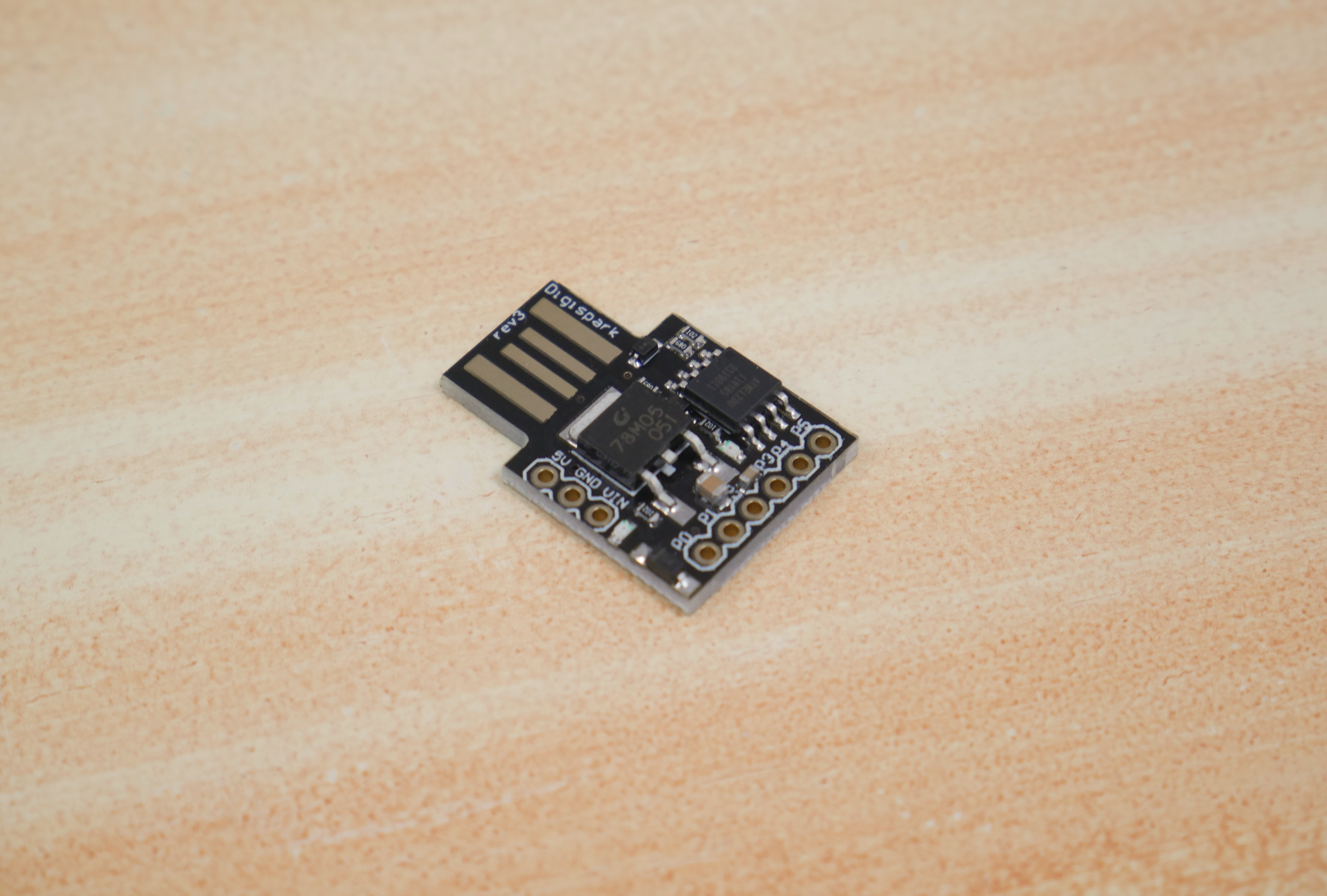
Just as most Arduino boards come with a USB port for programming and sometimes as a source of power, Digispark comes with an onboard USB connector that can be plugged directly into a computer for programming of the device. The board can be powered via the USB port which will feed 5V to the board or from an external source via its VIN pin that can accept ~7 to 35V which will be regulated down to 5V through an onboard 78M05 voltage regulator.
If you are using more than 100 LEDs use any other powerful MCU
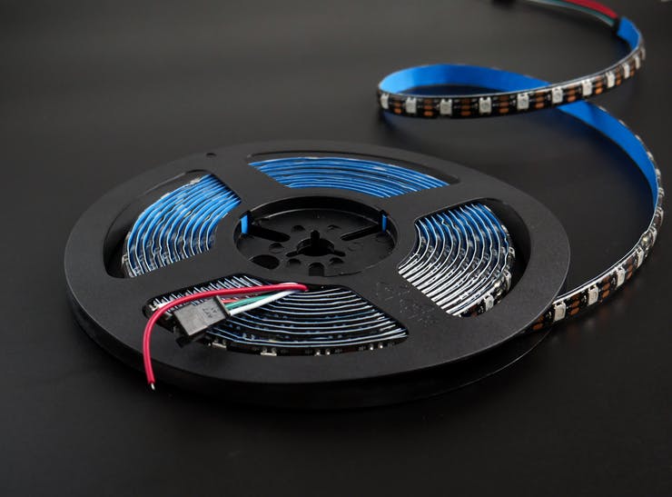
For lighting up this project, we are using WS2812B 5V Addressable RGB LED Strip is extremely flexible, easy to use and each LED of the strip can be controlled separately by using a microcontroller. Each LED has been equipped with an integrated driver that allows you to control the color and brightness of each LED independently.
The LED strip should be powered using a 5V power source, and Digispark will also work in 5V. Our device needs around 30 Led's, so we need at least 1.5 A current for the power supply. 5V 2A AC to DC adapter will do the job.
We also used some thin silicone wires for making connections.
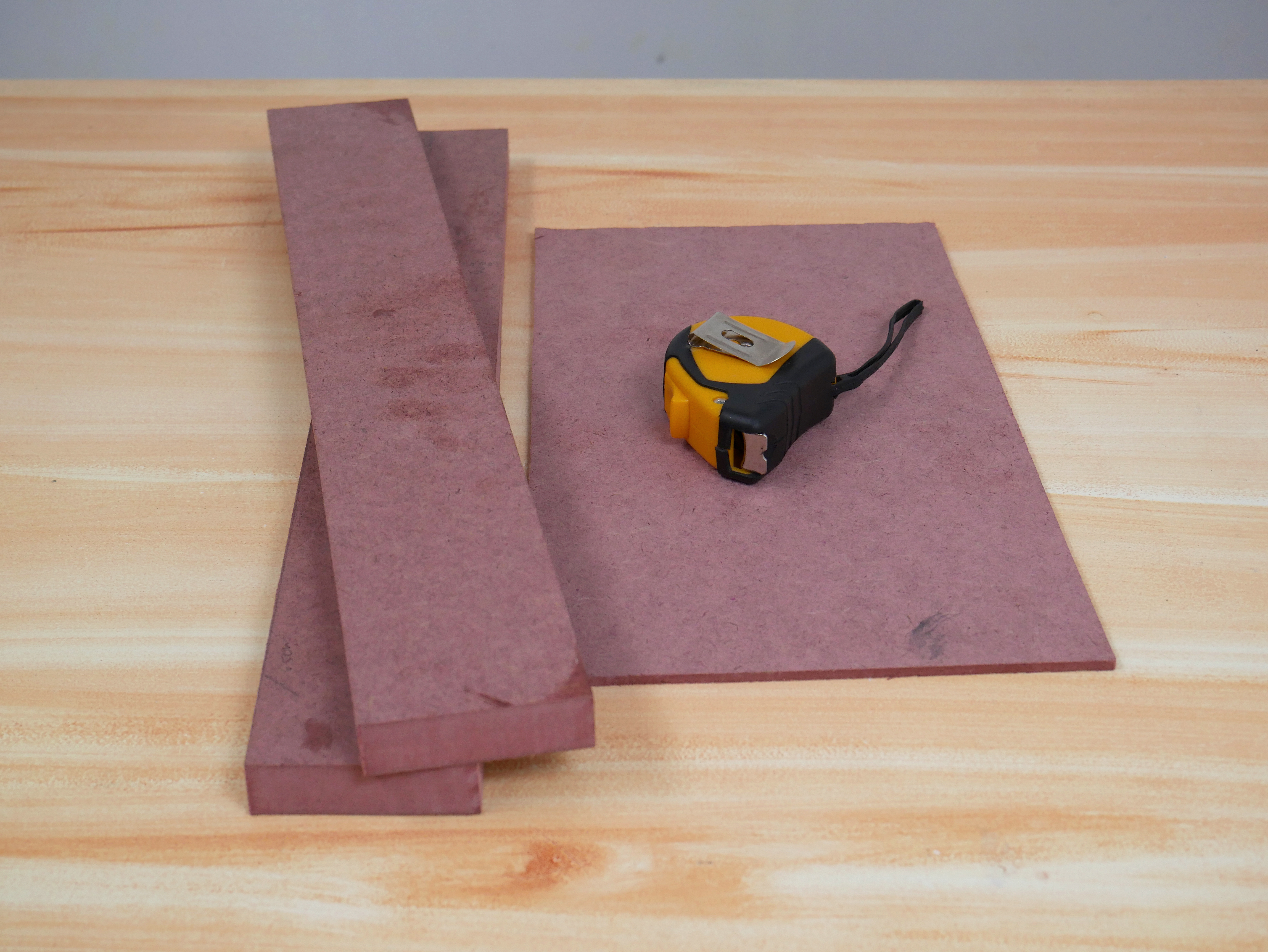
For this project, we are using leftover MDF pieces from the earlier project. The proper diffusion is possible even if there is a considerable distance between the acrylic and the MDF board. That's why we used this wood, with this much thickness.
Testing
For uploading the code from Arduino IDE to Digispark Attiny85, just follow the instructions here.
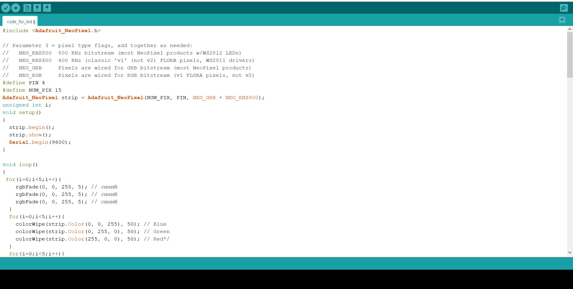
Then we uploaded our code to the MCU. You can grab the code from here.
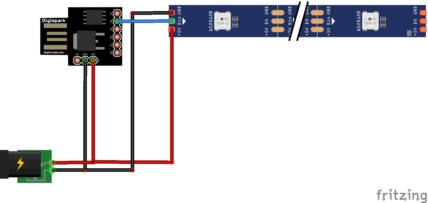
After, we connected the components as per the schematics and powered it up.
The Led is working flawlessly. The library here used is Adafruit Neopixel. You can read more about it here.
Now let's move on to the woodworking part.
Edge to Edge Gluing
So we can join these two MDF boards to get the required length for the project, using instant glue. Then we used an F clamp for creating more inward pressure. After reaching the final strength we removed the clamp and sanded...
Read more »
 Adam Redfern
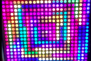
 AdroitConfusion
 Angela Sheehan
 Sander van de Bor