El Juanan
I'm pretty sure this is a prototype, it has prototype pcbs, components soldered one in top of another, a microammeter built in and a weird connector with no labels anywhere.
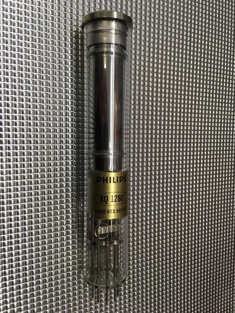
It is indeed a very beautifull piece, I date it from the mid 70s, according to the model of the Vidicon.
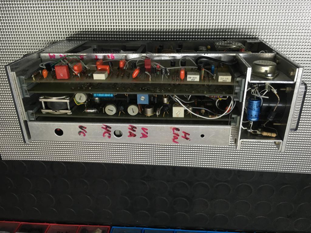
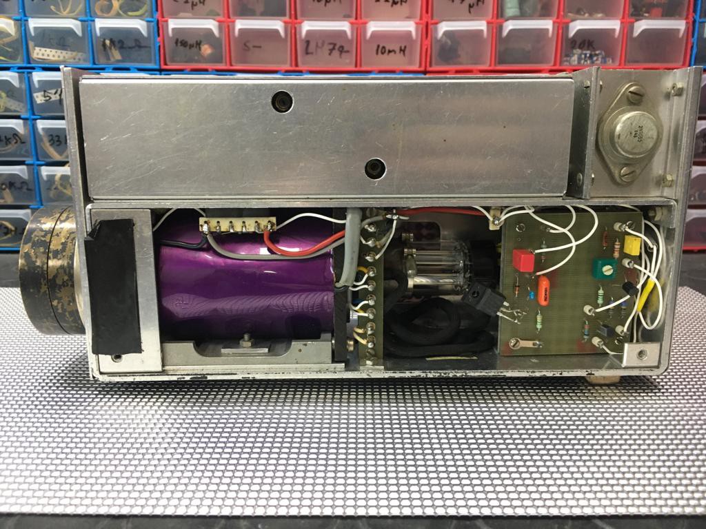

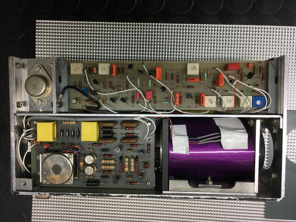
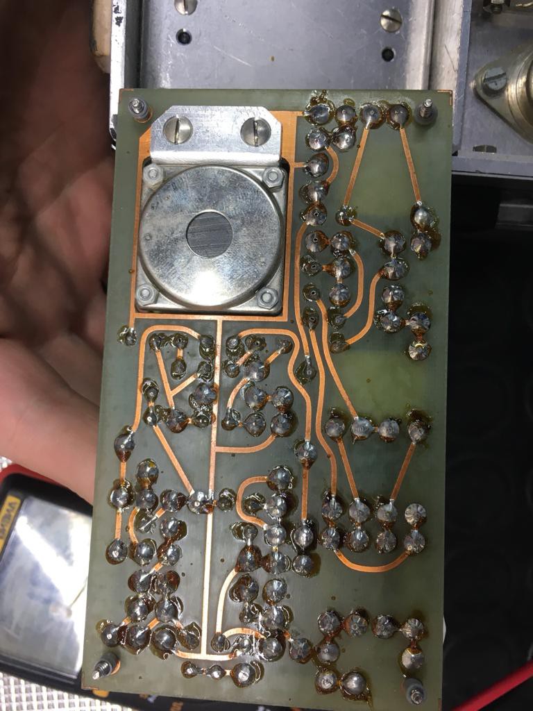
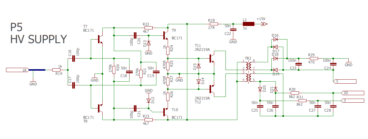
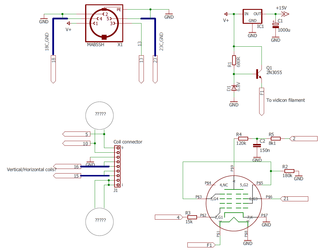
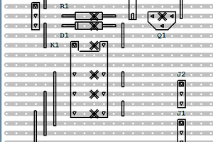
It has a total of 6 boards and a little bit of wiring which has no labeling at all. The Vidicon uses magnetic deflection and not electrostatic. This thing needs to generate high voltages for the anode of the tube, the focus, etc, and I'm pretty sure the board with the transformer (the one you see in the image above) is the one in charge of generatig those voltages.
The idea of this project is to obtain the diagrams of all of the boards, and maybe have a clue of what each one does. I don't expect this thing to give a standard video output signal, I don't think you can achieve that only with a bunch of transistors, but I expect it to drive correctly the defelction coils and the tube. Maybe this thing never worked at all, but it will be fun to find out.
 Niel Malan
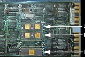
 Stefan Lochbrunner