 Pixelbo
There is 2 types of cameras in school, I've borrowed one of them the Pelco Esprit 4036.
The video encoder is also from the school, it's a Bosch VideoJet XF E.
A dream school project: control one or more cctv cameras with only a arduino
Already have an account? Log in.
To make the experience fit your profile, pick a username and tell us what interests you.
There is 2 types of cameras in school, I've borrowed one of them the Pelco Esprit 4036.
The video encoder is also from the school, it's a Bosch VideoJet XF E.
Ok so what's new?
Well there is 3 chapters:
Ok so to resume, the lib need to know which command we are sending to correctly parse the input data (e.g: if the command is SET_PAN , the lib must compute the given angle to hex values to transmit)
The solution: have a list with every special case!
const byte CMND1[5] PROGMEM = {FOCUS_N, IRIS_O, IRIS_C, OFF, ON}; //List of all commands that go on the byte3; a list with command 2 is not required, a bit of logic please
const byte DATA1[2] PROGMEM = {PAN_L, PAN_R}; //List of all commands that use ONLY the DATA1 for data pass

const byte SETPOS[3] PROGMEM = {SET_PAN, SET_TILT, SET_ZOOM}; //List of all command that require an MSB and LSB

const byte DATA_BOTH[5] PROGMEM= {PAN_L_TILT_D, PAN_L_TILT_U, PAN_R_TILT_D, PAN_R_TILT_U, WRITE_CHAR};//List of all commands that use the DATA1 and DATA2 for data pass (excluding the SETPOS' commands)

const byte RESP_CMND[3] PROGMEM = {RESP_PAN, RESP_TILT, RESP_ZOOM};

const byte QUERY_CMND[3] PROGMEM = {QUERY_PAN, QUERY_TILT, QUERY_ZOOM};

const byte PRESET_CMND[3] PROGMEM= {SET_PRESET, CLR_PRESET, GOTO_PRESET}; //will I use it?
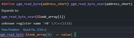
The problem: Getting a value of progmem's flash isn't what it is.
If I want to compare the Command PAN_L to DATA1, I can't use a loop with DATA1[i] (with i incrementing)
why? Because progmem is maintained by a library: pgmspace.h (more on the arduino refenrece)
The solution: After reading a bit of documentation, you actually need to do this:
pgm_read_byte(&DATA1[i]) //(Demo purpose not in the lib)
I swear the title is not a Clint Eastwood reference O_O
What do we do with a functionning library, we test it!
I had keypad laying around my place so I plugged him in the esp and onto the testing and good news!
The 2 modules that generates RS485 works with the 2 mains architectures (avr and esp32)
Ok little demo video right there /\
With the library completed ( I strongly suggest you to see the github repo, there are new examples, etc)
I updated the library.properties and the created keywords to create style coloring:
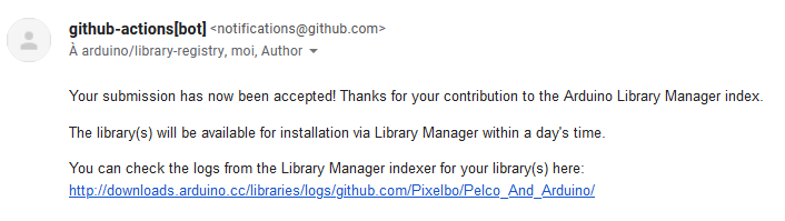
So with this and that next step, uploading it to the arduino library manager (again thx because the documentation is really great)
A few hour later:
Well now you can download it from the library manager ! (it's so coool)
Well with this project log finished, until next time!!!
This has been a long time, I have a lot of work for school in the background so this project slows down a bit but still persists!!
What I haven't done is the physical board due to lack of time.
But what I have done is a lot of coding!
You can see the progress in the GitHub repo but here's a little summary:
-More commands
-More fail-safe check
-More readability with the constants.h file
-3 examples
-You can now set the pan and tilt position with angles!!!!
If you are worried about the control panel well I will be making this in the vacations so in about 3 weeks.
During this time I'll update the code to feature request commands and more testing is required!
Until next time!
Hello!
I've made some big modification to my Arduino library.
It can now control the camera with only one module with the switching of the RE and /DE pin on the module.
I haven't tested yet all feature, so I can't say for sure if it works but here is what the library should do:
-Sending a basic command with reception of the acknowledgement message from camera
-Sending a query and decoding properly the response
-Sending a raw text command like so: "FF 01 00 04 3F 00 44"
It is already the end of the log, a short one for sure but be sure to check the github!
Next I'll build a mini desk control to test all feature!
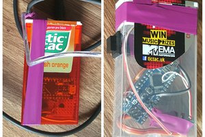
My vacation is now over, I had a little tchat with my teacher and we figured out that the most "easy" way to have multiple cameras without denuding the already present wires is to have:
-A pair of wires with RS485 bidirectional
First of all we need to configure the camera via the dip switch, we have 3 possible modes:
(TX is here from Arduino to camera and RX camera to Arduino)
-RS422 with 5 wires (GND, TX-, TX+ and RX- ,RX+)
-RS485 with 4 wires (TX-, TX+ and RX- ,RX+)
-RS485 with 2 wires (TX-, TX+ OR TX-, TX+ and RX- ,RX+)
Of course we want RS485 with 2 wires, however we encountered a problem: the TX module was supplying 5v (in idle state) to the camera even when it responded (For more explanation).
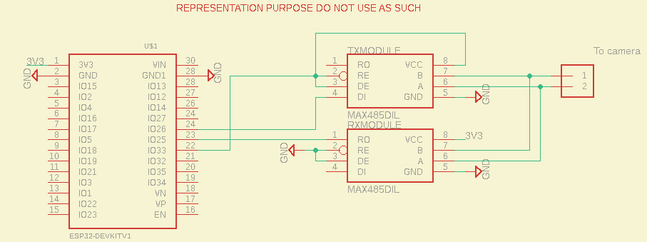
The solution to this problem: control the TX module's idle voltage with pinout!
I use an esp32, so the pins delivers 3v3 but that's not a problem because the chip function fine with 3v3 and the camera still works (The voltage differential is enough big)
So I grabbed my jumper wires and a schematic like this:
You can see that the TX module's Read Enable, Driver EN and vcc is controlled by tht IO33.
This module pins work like this
| VCC | RE pin | DE pin | Module state |
|---|---|---|---|
| 3V3 | LOW | LOW | Receiver |
| 3V3 | HIGH | HIGH | Transceiver |
| 0V | HIGH | HIGH | Residual voltage |
| 0V | LOW | LOW | Nothing |
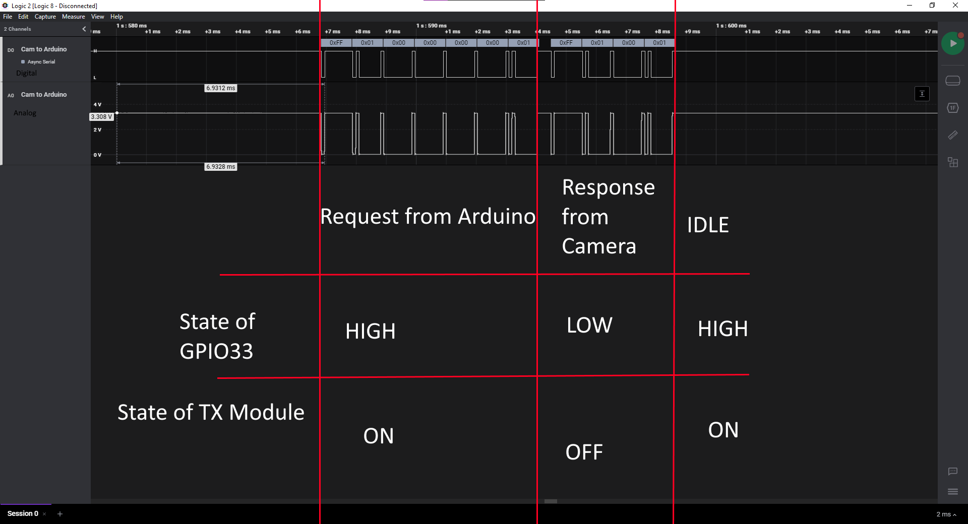
but what is the is the result, here are the result in UART communication from RX module to Arduino:
Still "One problem": we detect also the TX module transmission but that's not a problem because we can filter it out in the software:
Well that was all for today, see you next for Software Improvements!
Read more »Hello again fellows followers, thank you so much for supporting me for this project,
If you don't know it, I'm French, that means vacations for me.
I think I worked hard enough on the camera for now (I have other projects to do in the background too)
With this project I want to create a control board for cameras, that will work on both cameras models at school (my main inspiration)
Of course this is not a brutal stop, I'll be back at the start of school where I'll be discussing with my teachers about hardware and software.
So stay tuned and remember:
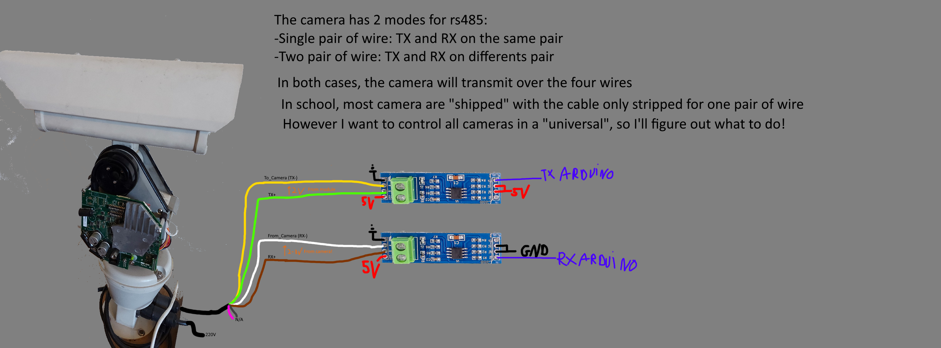
Hello again, here a couple of images where I try to explain to you how it works:
If you can see well, between the TX- and TX+, there is a 2V coming from the rs485 module, it is a "problem" because when the camera responds at the query on the same pair of wire, the signal from the camera is cut out by this 2v (lowered to a volt difference about 200mv).
I'll figure something out for next time!
See you next time !
Oh my god it's hard!
Anyway, I've been working on an arduino library for this project that will make my code beautiful.
You can find it here: https://github.com/Pixelbo/Pelco_And_Arduino
Feel free to help me cause I may be a talented programmer I'm still to young to do a proper library.
PS: it is still in development so except update, examples, etc
It is also my first library so it was hard but life is.
A short log for exposing a main problem: the rx pair of cable have too much noise (the ones that comes from the camera)
To be precise when I input a command for the camera, it drives the motor and just after I call a query for the pan position but the motor has just been driven so the cable have too much noise leading to incomplete result on my esp.
If I don't run the motor it works fine but there is still too much noise:
I know that rs485 work with voltage potential so I know that the cables at school are all the same so there is no ground connection on the cable and I won't make one for now.
So what I need to do here is to find a solution with the modules.
See you next time !
Oh, did I spell it wrong?
I mean the two components for the transmissions over the camera.
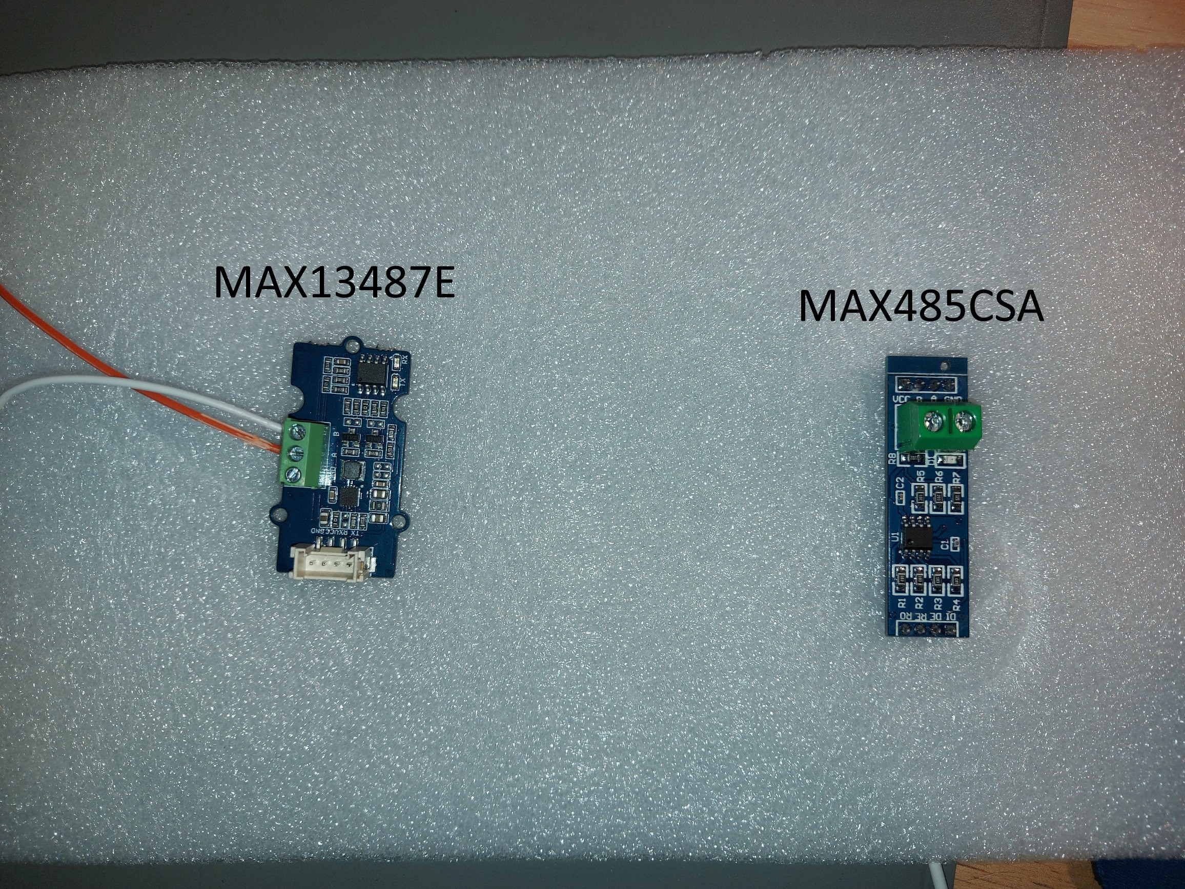
Since the protocol used is rs485, I was given two very different modules, one with the max485-CSA chip and the other with the max134-87E chip:
You can have a look a the documentation here: MAX13487E and MAX485.
To summarize: the left module comes with a groove adapter, you need only to wire tx and rx, however the right module need to be wired to be in transmitter mode or receiver mode and that is the major difference the left one an switch between these two modes automatically where the right one can't.
If you wonder why the groove module has twice as much components compared to the max485 it's because it has a current Buck-Boost converter, which enable the module to be driven in 3v3.
But one thing strange is that the voltage differential from the output of the max485 is higher than the max13487E.
We know we need two modules, one for transmitting the information and one for receiving.
Or do we need two? We'll see that in the next log where we will be choosing between the two modules
Thanks to the various websites on the net I was able to get the protocol that Pelco used (Thanks to my teacher to who found it before me).
The protocol is very simple, it's called PELCO-D and it work like that:
| Byte0: Sync | Byte1: Address | Byte2: Command 1 | Byte3: Command 2 | Byte4: Data 1 | Byte5: Data 2 | Byte6: SUM |
| Always FF | In our case 01 | see below | see below | see below | see below | sum of everything except sync modulo 100 |
The list of commands available can be found here.
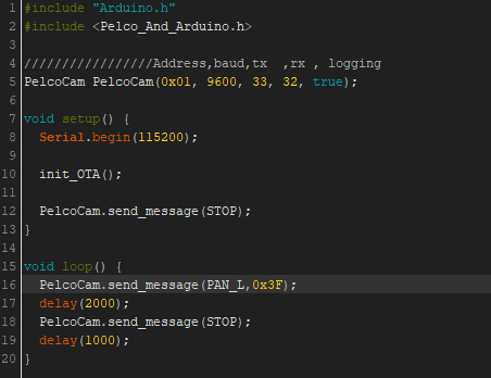
So with that in mind I wrote a little program on arduino and set 3 messages:
The first was turn to left then was stop and after 2 seconds, it was a query to the pan position.
And to my surprise, it worked!
However what about the query, so I hooked up the oscilloscope on the wires and began searching for the response.
But if you remember well, there was a pair of cable that was for 3v and gnd. So I probed those cables and then bang, a response:
So we have a pair of cable for TX and one for RX, only one pair of cable remains unknown.
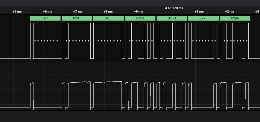
Having figuring out that reading a rs485 protocol on oscilloscope was hard, I switched onto a logic analyzer on my computer.
And here is the response to my query:
So if you watch closely, it is supposed to be response claimed by the website up above.
So stay tuned because next time, we'll update the arduino code and understand what is the content of the response!
 Ok problem fixed


 davedarko
 krzysztof krzeslak
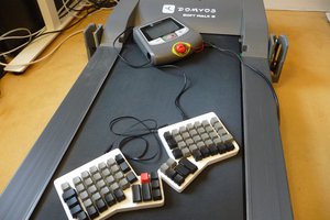
 PixJuan
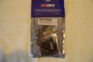
 phillicom