 Sam Ettinger
Two low-cost options for TPI programming are the USBasp (with the latest firmware) or the TPI Programming Arduino Sketch by Junk+Arduino and others. Neither the USBasp nor the Arduino has a pin available to output 12V, of course. That requires some extra hardware.
The task is easy to summarize. Create a new signal that produces 5V when RESET produces 5V, and goes to 12V when RESET goes to 0V. On YouTube, fVripple made a very good one with an optoisolator and a benchtop power supply, but I wanted to stick to parts I had on-hand and make it more portable.
UPDATE: somehow I missed that Nick Sayer made a very similar little board two years ago, and sells them on Tindie! Sincere apologies for not seeing it and listing it as prior art.
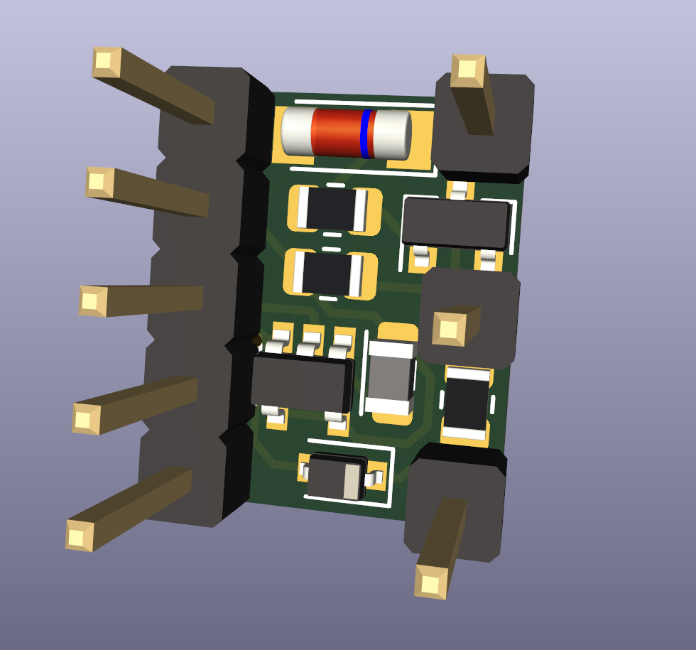
Anyway, this is what I came up with:
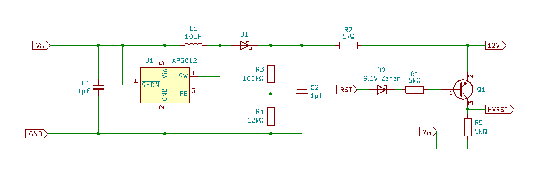
An AP3012 boost converter gives us 12V all the time. While RESET is HIGH, the forward voltage of the Zener diode is high enough that no current flows through the PNP BJT and the output is equal to RESET. When RESET goes LOW, current flows through the 9.1V Zener diode, driving the output to 12V. The 5kΩ resistor value is not a precise one; I think I used 3.3kΩ in practice. And I broke out the 12V signal in case I ever wanted to use it for something else, I dunno what though.
To actually use this schematic, I made two designs: one to go with the USBasp and one to go with the Arduino TPI programmer. I was very sleep-deprived and made some silly design choices.
The USBasp HVTPI tool
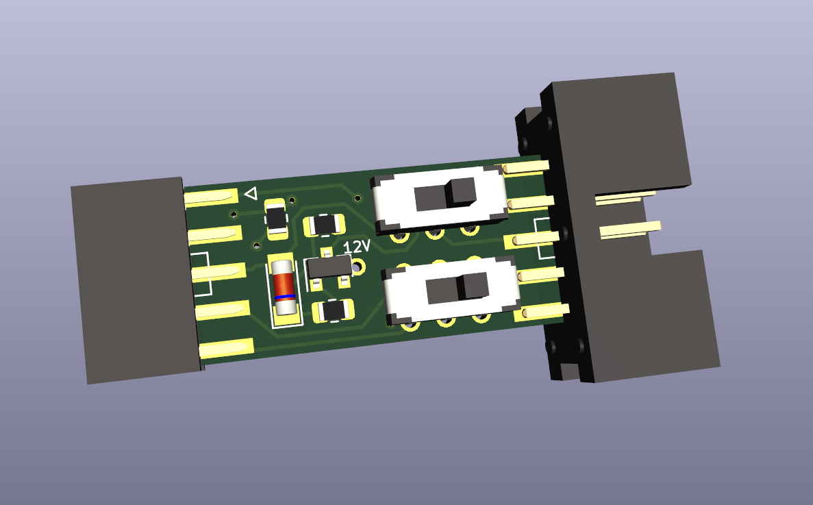
The USBasp HVTPI tool mates nicely with its 2×5 IDC headers. There are two DPDT switches, one to switch between 0V reset and 12V reset modes, and another to combine the two data lines as described in this application note:
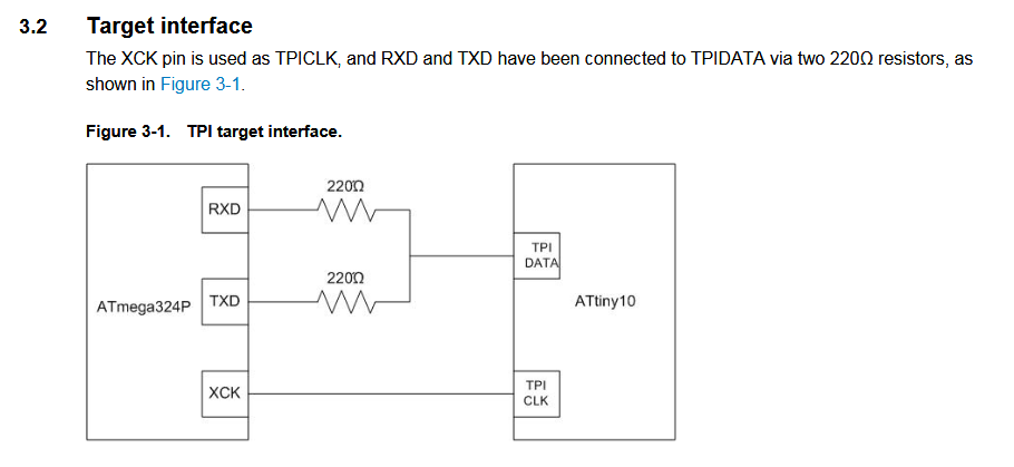
These resistors are not always necessary, which is why they can be disconnected with the switch. The USBasp expects a circuit with a programming pinout like this:
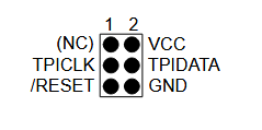
Consequently, the line that is normally labelled "MOSI" acts as the bidirectional line when the USBasp does TPI stuff. This becomes a problem if you are using a circuit that was designed for the Atmel-ICE, which expects a programming pinout like this:
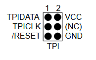
Both configurations are handled equally well by the 220Ω-resistor switch.
Using the HVTPI tool is as easy as normal TPI. As far as your computer is concerned, there is no difference between this and a normal TPI setup, so no instructions or makefiles have to change.
The USBasp HVTPI tool
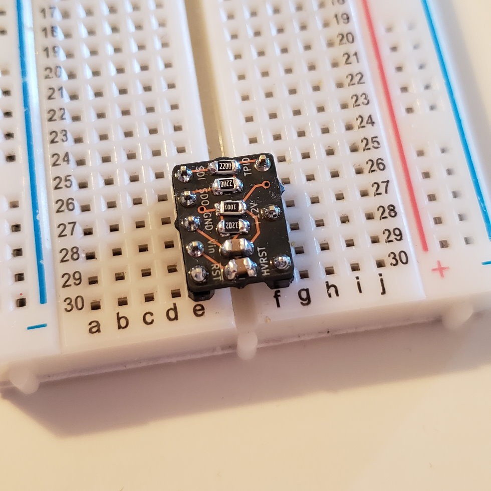
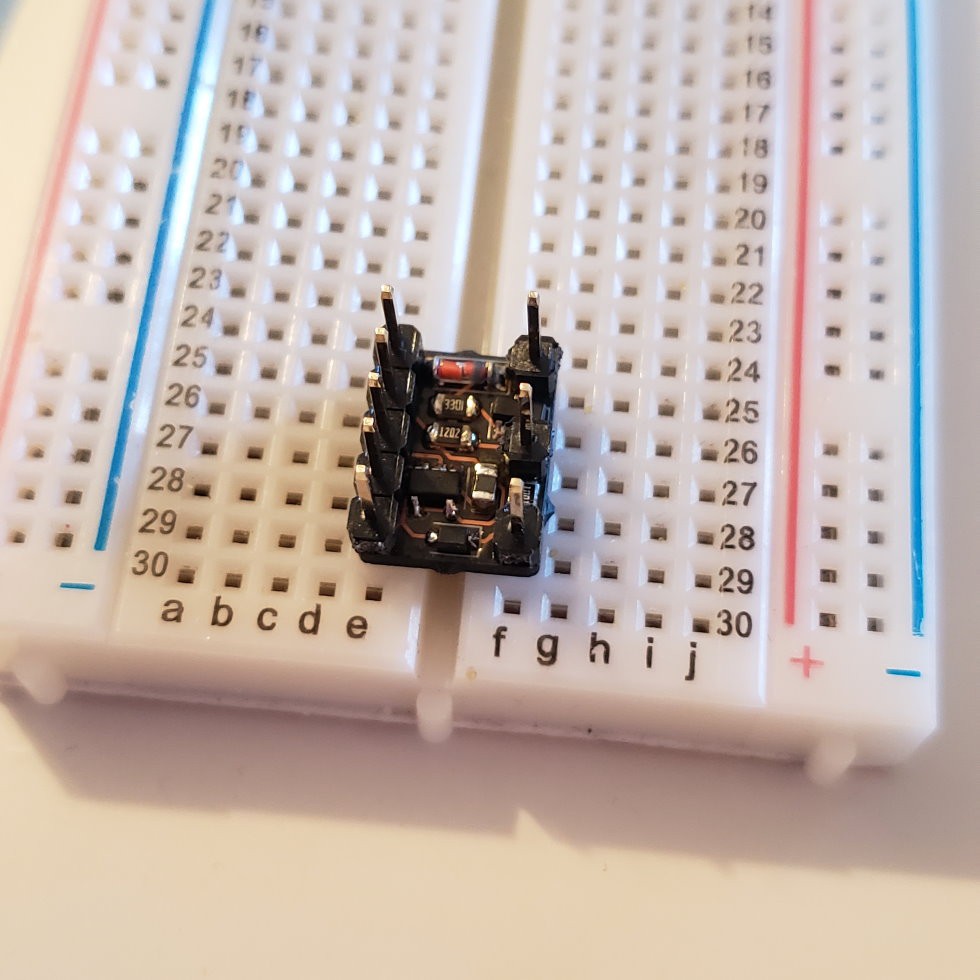
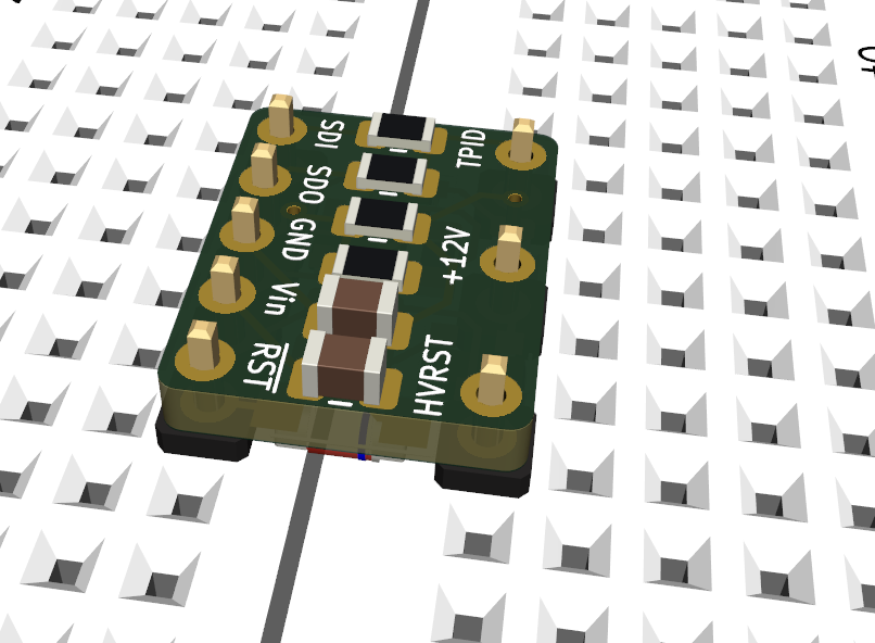
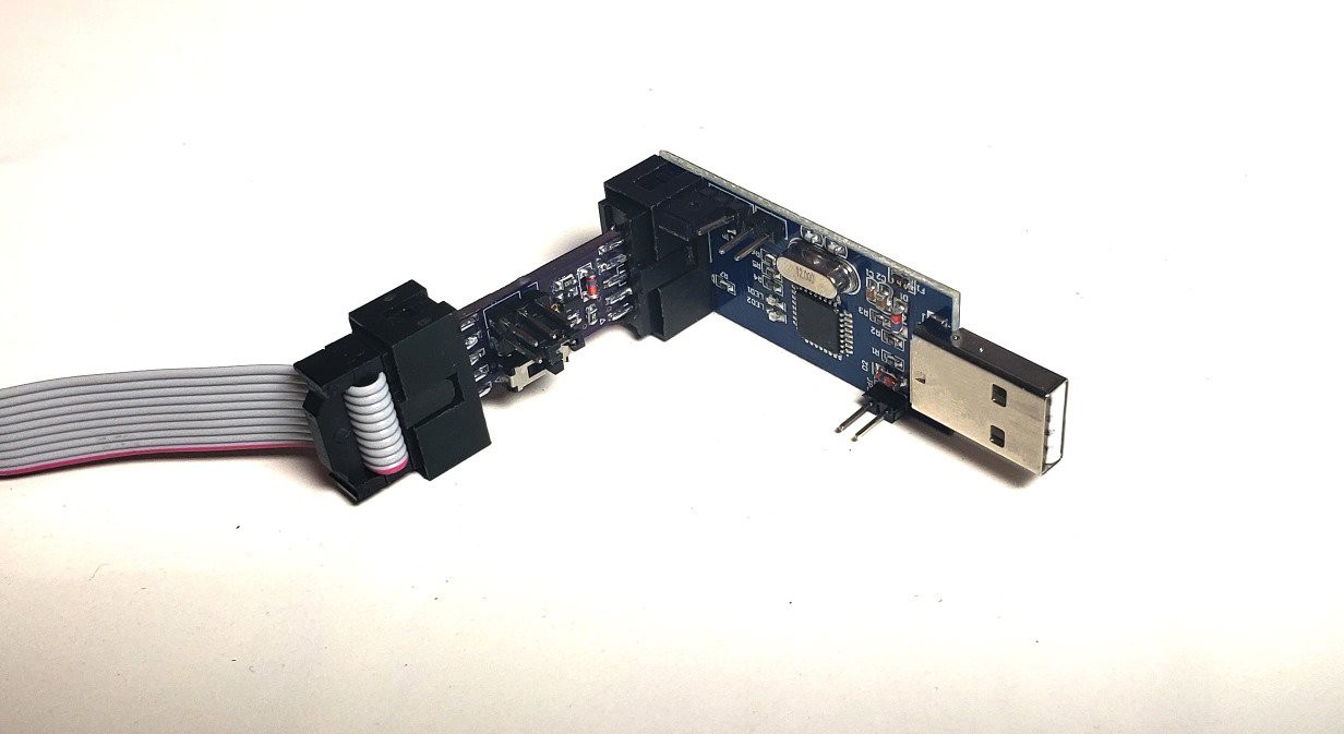
The Arduino-compatible programmer is designed to sit in a breadboard. I originally designed it very skinny, with the HVRST line sticking up like so:
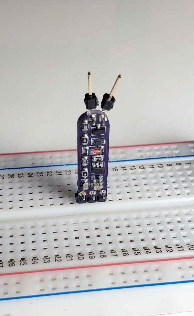
This is not very helpful, so later I went back and put it in a more reasonable 10-DIP layout. Because the Arduino program expects both MISO and MOSI lines to connect to the TPI DATA line via 220Ω resistors, I built that into this board as well. Again, there is no need to make any changes to the normal TPI programming workflow. I know the Arduino sketch has some "HVP" options available, but with this board they are wholly unnecessary.
I'm happily using these with both the USBasp and the Arduino for HVTPI programming. I had a hard time finding good resources for HVTPI and had to do a lot of learning-by-doing, but hopefully I can pass that knowledge along and save someone some trouble.
Note to self
After setting the ATtiny4/5/9/10/20/40 fuse bits to `0xFE` (or whatever) to enable 12V reset, avrdude can't just overwrite the fuses with `0xFF`. Using the flags
-x section_config -e will clear the bits.