 Zach Armstrong
Preface: PCBs and parts
While building a Tesla coil on a breadboard is possible, you may find it frustrating and more prone to issues. For these reasons, I designed a custom PCB for this circuit which can be downloaded here: https://drive.google.com/file/d/11MJa5GTr7-2HdkTSjfyX_S2E6avNrjo8/view?usp=sharing
This .zip file should contain everything from PCB gerber files to a full set of instructions with a parts list (complete with links)! Be sure to check it out, the download is totally free, so you have nothing to lose!
How it works
The circuit accepts a feedback signal either from antenna feedback or from a feedback winding (“ANT.” and “FEED.” on the PCB, use whichever method you prefer. I recommend antenna feedback for beginners). This signal is then filtered, limited, and cleaned up by a resistor, capacitor, and diode clipping array. After this, the signal passes through a 74HC14 Schmitt trigger, which converts the somewhat sloppy signal into a more functional squarewave that matches the resonant frequency. This squarewave signal is then sent to a pair of UCC gate driver ICs (one UCC37322 and one UCC37321), which amplify the signal. These gate driver chip feature enable pins, which basically act like the on-and-off switch. If we feed the interrupter’s signal to the enable pins, we can control the Tesla coil’s pulse width and frequency (BPS).
The resulting interrupted signal from our gate driver ICs is finally sent to a small device known as a gate drive transformer, or GDT. If properly assembled, the GDT converts the single 12V signal from our driver into two 18 volts signals, which are perfect for switching our transistors. By phasing the GDT correctly, the transistors will switch the DC voltage from our power supply across the primary coil at the resonant frequency. This causes a massive voltage to be induced in the larger secondary coil, which causes the beautiful display of homebrew lightning that all Tesla coil fans know and love.
Dual resonance and the flip-flop
Up until this point, I’ve basically described the construction of a classic SSTC. So, what sets this build apart as a DRSSTC? There are actually a few things: first, the resonant capacitor. The main drawback of solid-state Tesla coils like the LabCoatz SSTC 2.0 is that their current is limited by the primary circuit. The primary coil has a certain inductance, and that inductance causes a kind of resistance specific to AC signals, known as reactance. Fortunately, there is a trick to eliminate this unwanted reactance, and that is to add a capacitor of a specific size in series with the inductor. If the capacitor-inductor combination has a resonant frequency matching the frequency being applied to it, the reactances cancel, leaving only the very small resistance of the wire itself. This is, in fact, the main principle behind dual resonance: the goal is to have the primary circuit tuned so that its reactance is near zero, which allows the resonant signal produced by the solid state circuitry to flow unimpeded at very high currents. Higher primary currents result in higher secondary voltages, and therefore longer sparks.
Unfortunately, making a DRSSTC isn’t as simple as throwing a resonant-size capacitor into any old SSTC. If you saw the tutorial for the LabCoatz SSTC 2.0, you might remember that I had to avoid primary impedances below 6 ohms to keep the IGBTs alive. So how do DRSSTCs get away with nearly zero ohms of impedance? As it turns out, the secret is in the switching: for a DRSSTC to function properly without failing, it is necessary to soft-switch the transistors. This is where the flip-flop comes into play: essentially, it prevents the interrupter from shutting off your transistors while current is flowing, which could kill them if you’re running in dual resonance.
For best results with a flip-flop, primary feedback is recommended over secondary or antenna feedback. If you choose to use primary feedback though, you’ll need your primary circuit to be tuned fairly precisely, otherwise your coil will behave rather poorly. When I built this circuit, I chose to stick with antenna feedback, just because I’m used to it and it’s easy to set up. Using secondary feedback does make running in dual resonance somewhat more dangerous to the transistors though, since the secondary signal isn’t precisely synced with the primary switching, which prevents the flip-flop from doing its job perfectly. If you want to try dual resonance with secondary feedback like I did, I recommend detuning your primary circuit somewhat. This will allow the impedance to be low, but not low enough to cause significant overcurrent issues and harmful voltage spikes.
To further protect the IGBT transistors, I also recommend soldering 400V TVS diodes across the collector and emitter pins. Even with a flip-flop and some detuning, high voltage spikes are almost inevitable in a DRSSTC, so it is best to be prepared! The circuit will run fine without TVS diodes, but the IGBTs may die sooner than desired. Unfortunately, the PCB I made didn’t have enough room to fit connection points for the TVS diodes, so they must be soldered directly to the IGBT pins.
Staccato and QCW: The secret to BIGGG SPARKS!
Let’s face it: you aren't viewing these instructions to learn about any old SSTC or DRSSTC. You want to learn the secrets of QCW (Quasi-Continuous Waveform) so that you too can transcend the mortal realm of Tesla coiling and produce the longest sparks possible! Well, you’ve come to the right place! But before I fully divulge how this circuit achieves its ridiculous spark sizes so easily, let’s take a moment to look at how traditional QCW coils do it:
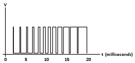
The secret to QCW coils is voltage ramping: QCW coils are just ordinary DRSSTCs that have their input voltage ramped up from zero to max (usually 340VDC) over a period of 10-20 milliseconds. In a "true" QCW coil, this is accomplished with PWM: a programmable circuit such as an Arduino creates a moderate-frequency PWM signal (15-30kHz) that increases its pulse width from zero to 100% over a period of a few tens of milliseconds:
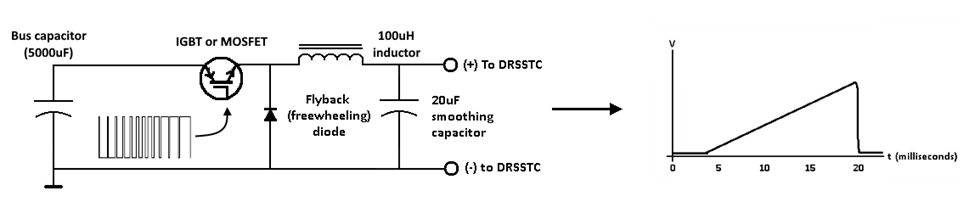
This signal controls an IGBT or MOSFET in series with the power supply (which is usually a very large bus capacitor). The transistor chops up the power supply current and passes it through a large inductor (about 100uH, or slightly more) to smooth out the 30kHz noise. A smoothing capacitor (about 20uF) helps keep the voltage steady, and voila! A nice, clean voltage ramp!
People who have experience with electronics may recognize this topology as nothing more than a fancy buck converter. Of course, to drive the transistor properly, some circuitry is usually used in addition to the programmable PWM generator (check out the Loneoceans website for some awesome QCW designs and info). Overall, the complexity and cost of such setups tends to limit QCW to only the more experienced individuals and coilers...
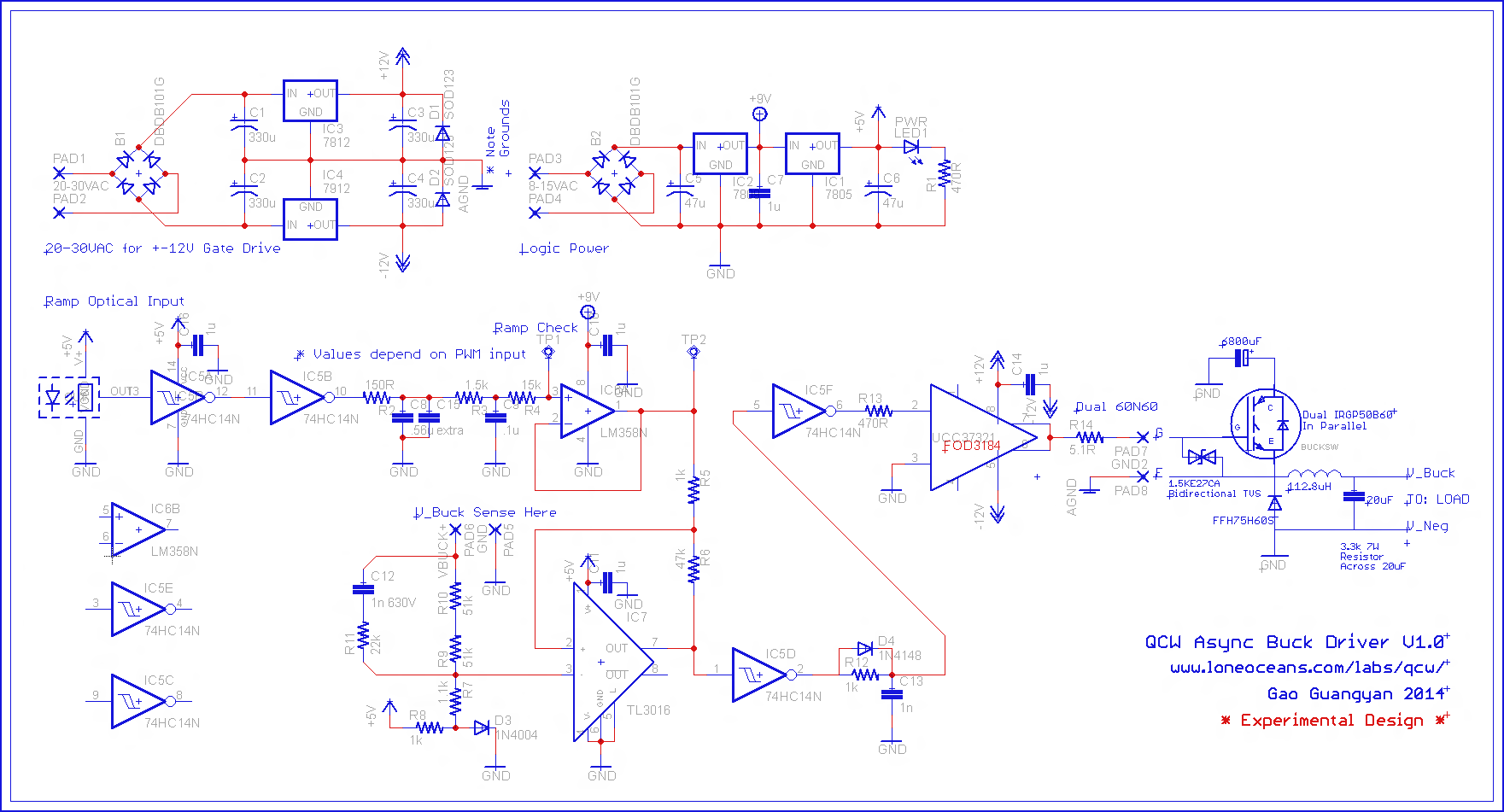
...so why waste precious time and money trying to set up a “true” QCW when you can just use the voltage ramps that are already available to you?
QCW was actually developed from an earlier technology used by the vacuum tube coil community: staccato interruption. A staccato interrupter is one that reads the AC signal coming from your wall socket and turns the coil on only when the rectified voltage is ramping up:
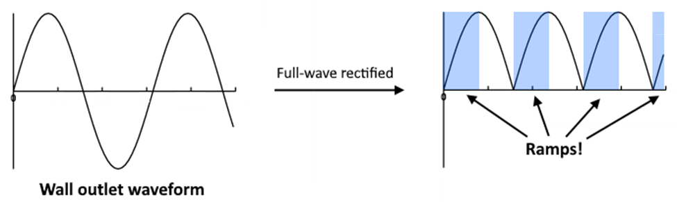
Since the electricity from standard wall outlets runs at 50-60Hz, you can easily get 4-5 milliseconds of ramp-up time, which is plenty to produce some wicked sparks! Additionally, each hump of the rectified sine wave also comes with a ramp-down time, which will allow the sparks to be quieter and thicker if utilized.
Build tips:
When building a QCW-type Tesla coil, there are a few main thing you can do to get the most from your design. Below is a generalized list of what to do and what not to do:
First, if you are building this circuit without the custom PCB, try to keep the inter-component connections as short as possible to reduce interference. Also, be sure to ground the negative rail of the low voltage circuitry: this is pretty important!
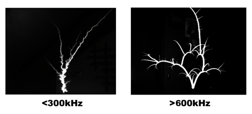
Next, try to make sure the resonant frequency is above 300kHz. Below 300kHz, the sparks tend to become more chaotic and less straight. In order to get the longest sparks possible, we want most of the coil energy directed into a single long spark as opposed to several branches or odd formations. If you like more branched and messy arcs, feel free to experiment below 300kHz, but if you’re going for distance, it’s best to stay above that range. It’s also best to stay below 600kHz. Above this point, the IGBTs will be much more stressed, and the sparks will become more curvy instead of straight. See the pictures below to observe what I mean:
Finally, try to use more primary turns, less capacitance, and tighter coupling. In a traditional DRSSTC, the opposite is usually preferred, but in a QCW coil, these traits are quite desirable. This might have something to do with QCW’s close relation to vacuum tube Tesla coils, which historically have followed similar design paths.
Troubleshooting:
While it’s totally possible for you to wire this circuit up and get it running well on the first try, you’ll more than likely experience some bumps. Fortunately, they are usually quite manageable and can be overcome with minimal effort. Here are a few of my best tips for troubleshooting this circuit:
If there is no output:
- First, check all of your connections. I’ve been totally lost on several occasions, and the culprit turned out to just be a bad connection
- Try bringing the feedback antenna closer to the coil. I’ve found my coil works best when the antenna is within a foot (30cm) or so of the secondary coil
- If tons of current is being pulled, it’s possible you wired your GDT wrong and killed your IGBTs. You may have killed them in other ways, but this is the most common way. It’s also possible that there is a random, accidental short somewhere in the circuit
If the output is very weak:
- Try swapping the primary coil connections. This almost always solves the issue
- The antenna might not be close enough, try moving it closer
- Check the secondary coil’s ground connection. If a coil isn’t properly grounded, the voltage at the top could be lower with respect to ground, and therefore yield weaker output
- Your coupling could be very low or your primary impedance could be extremely high. Try running some calculations and see if anything jumps out as strange or off
If you have “bad” output (unstable BPS or pulse width, weird noises, etc.)
- For some reason, the primary setup seems to affect this. Try lowering the coupling, increasing the number of primary turns and/or the resonant capacitor size.
- Interference may be the culprit. Make sure your PCB’s ground connection is good, or, if you’re building it without the PCB, make sure the low voltage negative/neutral is grounded. Also, try shielding the circuit with a layer of grounded metal or metal foil, this really helps!
CRANK IT UP!
Once the design, assembly, and troubleshooting are out of the way, it’s time to get your taste of QCW! When built properly, this circuit can easily produce sparks larger than the secondary coil itself, even without a resonant capacitor in series with the primary! Here are some stats from my unit with a 5-inch tall secondary (350kHz with a 6.5” toroidal topload):
- 120V input, no resonant capacitor: 8” sparks
- 240V input, no resonant capacitor: 12” sparks
- 120V input, dual resonant: 12” sparks
- 240V input, dual resonant: 20” sparks
- 240V input, dual resonant, no topload: 17” sparks
With 20” sparks from a 5” coil, this represents a monumental achievement in the Tesla coil world: the sparks are FOUR TIMES LARGER THAN THE COIL MAKING THEM! This kind of achievement is almost impossible to reach with most dual resonant, spark gap, or vacuum tube coils! Plus, this circuit also holds a whole host of other benefits:
- The sparks are extremely quiet, making it perfect for indoor operation
- Spark size is adjustable with pulse width (although shorter pulse widths tend to be louder)
- The circuit doesn’t use an expensive/bulky bus capacitor or thermistor
- Runs best with small, higher frequency coils, which are easier to make
- Small size, highly portable!
Not getting the spark lengths you hoped for? Here are some pro tips for getting the largest sparks possible from your design:
- Fiddle with the coupling. Intercoil arcing is not as common with this coil type, so feel free to experiment!
- Try using fewer turns on the primary coil. I found that it’s best to stay above five turns, however, otherwise the driver begins to act up.
- Play with different topload sizes!
- If you live in a 110-120V region, consider buying a 240V transformer to get the most out of your circuit. I used an 800W unit which can be purchased on Amazon.com for around $50.