 Dilshan Jayakody
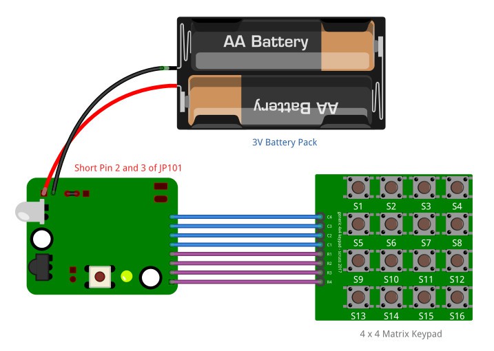
The hardware component of this analyzer is built around the STM8S003F3 MCU. It has 24LC32 EEPROM installed to store the captured IR signals. This unit is designed to operate with a 5V to 9V DC power source or a 3V battery.
Operating modes such as capture or replay can be changed using an onboard jumper on the PCB. These operating modes can change at any time without restarting the unit.
In addition to the IR clone PCB, the only external component needed to operate this system is a 4×4 matrix keypad. Most of the generally available 4×4 keypads can directly couple with this system.
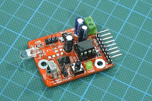
The dimensions of the IR Clone PCB are 41.2mm × 32.1mm, and it has been designed using both SMD and through-hole type components. In this given design, the TSOP1838 IR decoder has been used to capture the incoming signals. The output stage of this system consists of LD271, KCL5587S, or equivalent 880nm to 950nm (IR) LED. The 38kHz modulation signal required by the output stage is generated using built-in timers of the STM8S003 MCU.
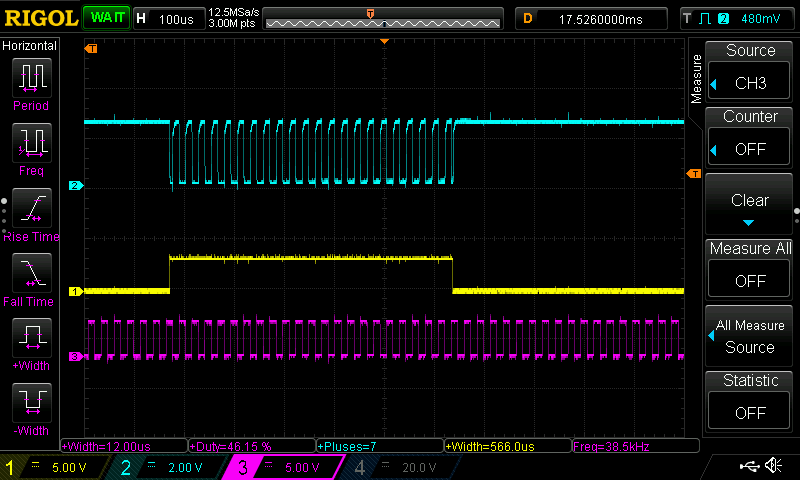
Captured waveforms stored in the EEPROM can be decoded directly using the IR Clone software provided in the repository. Using this application, the user can visualize and edit the captured signals. Both IR clone software and hardware supports up to 16 channels.
To transfer the EEPROM data to the PC, use any 24LC family compatible EEPROM reader or programmer. In our presentations, we used an inexpensive CH341A based programmer to read and write the 24LC32 EEPROM.
In addition to the IR Clone software, the repository also contains a sample Python script that exhibits decoding of EEPROM data.
IR Clone is an open-source project. All the documentation, schematics, PCB design files, firmware source codes, and application source codes are available at the project repository at GitHub.com.
 Mrinnovative
 Tyler Ward (Scorpia)
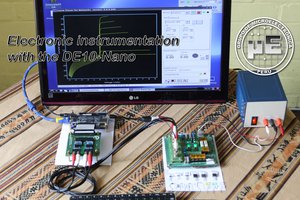
 Miguel Risco-Castillo