 J. Ian Lindsay
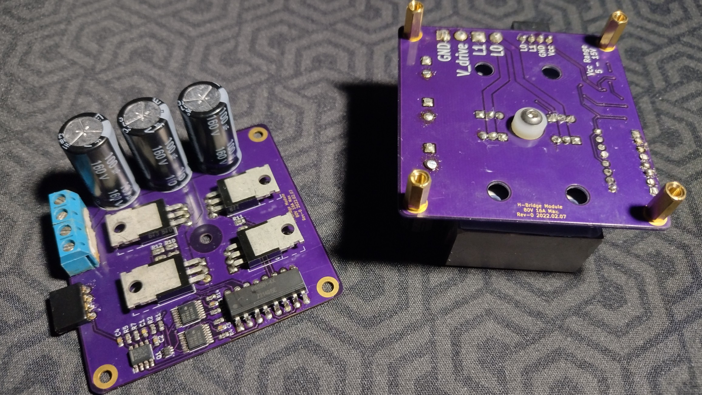
The voltage at each channel of a connected H-bridge mirrors the state of the respective logic input, with differential delay (enforced by a shift register). Changing the state of the logic input will immediately inactivate the active half of the leg, and will only enable the opposing half after a delay of 3-4 clock cycles.
All shift registers are fed from the same clock, which is generated by a 555 timer in astable mode. The length of the guaranteed deadband can thus be adjusted by choosing the RC values surrounding the timer.
The logic inputs are internally pulled low, thus assuring that the H-bridge initializes into a safe state (both load poles grounded).
All outputs from this module are active-high, and are thus not suitable for direct-drive of the P-channel of a given leg. Intermediary transistors are required.

 Dave Collins
 Peter
Peter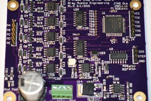
 Bharbour
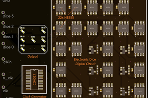
 Tim
Tim
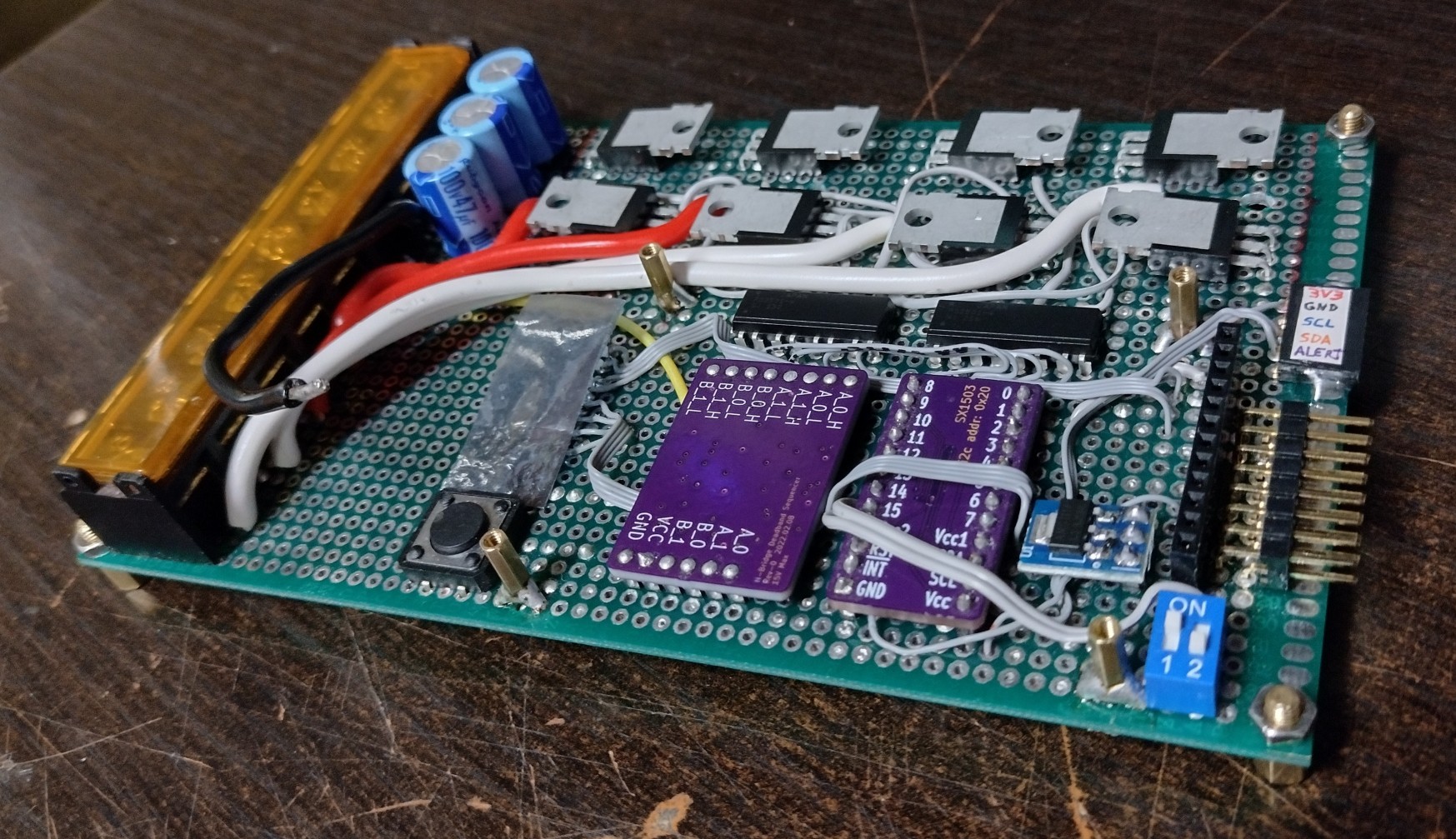
My first unit is assembled and tests good. But I am going to wait for my H-bridge implementation to show up before I declare it good enough to list on Tindie.