Step 1: The Installation of the Motor
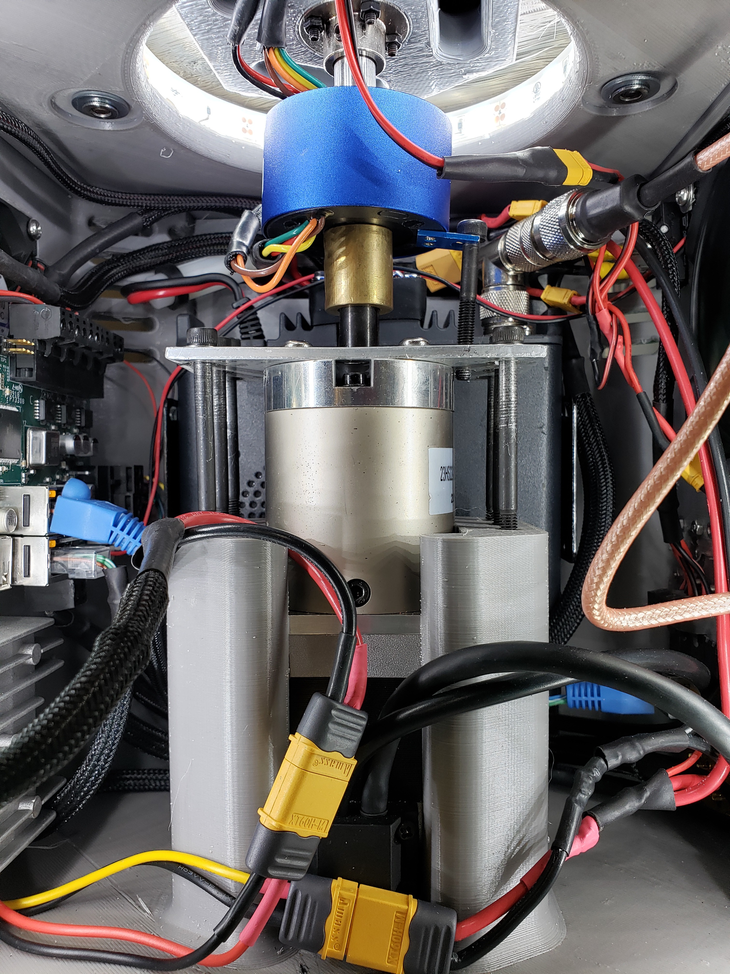
The installation of the motor was somewhat complicated. It included designing a center Pilon inside the enclosure to seat the motor. Then then manufacturing of a metal plate to bolt the motor to the pilon.
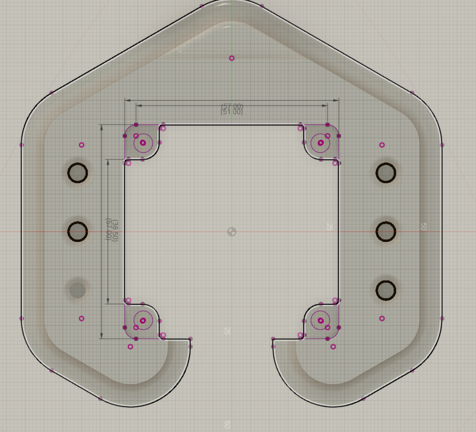
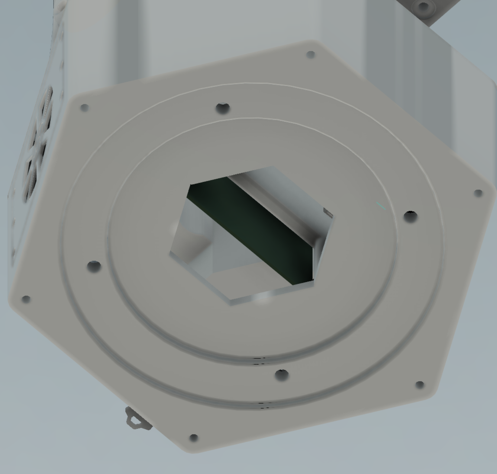
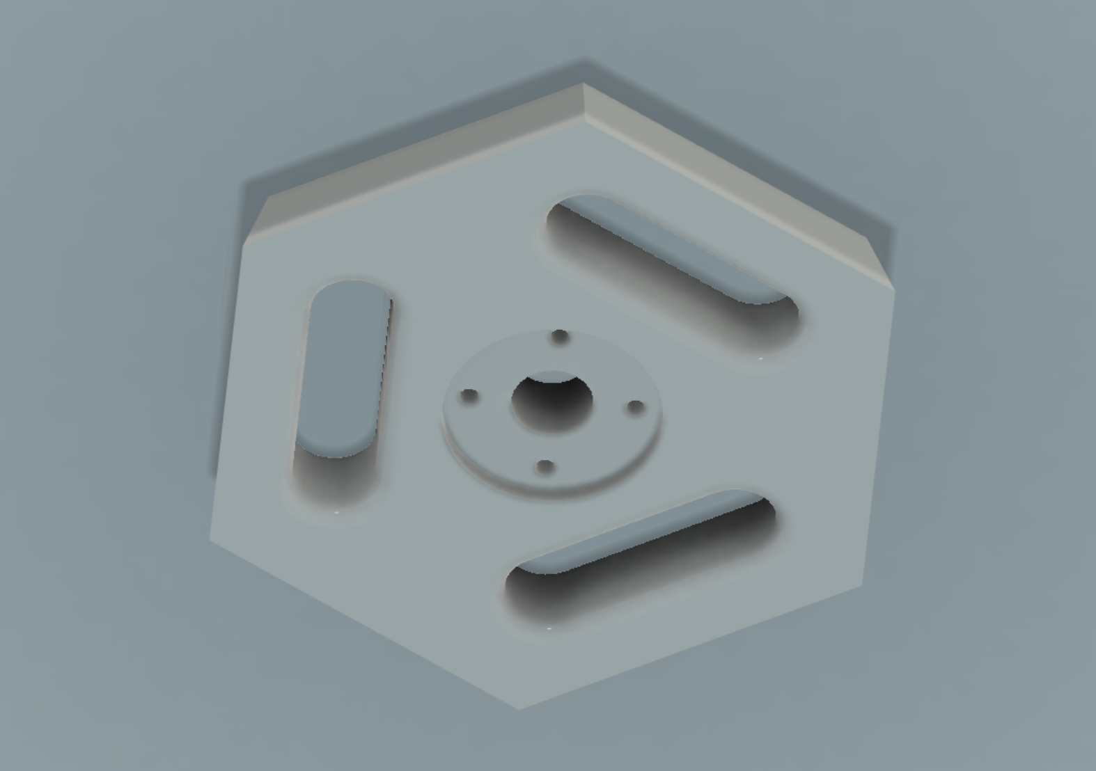
Next a large bearing was bolted to the top of the frame and the rotor was then bolted to the bearing. The top of the drive shaft was fitted with a hexagonal piece that mated with the bottom of the rotor.
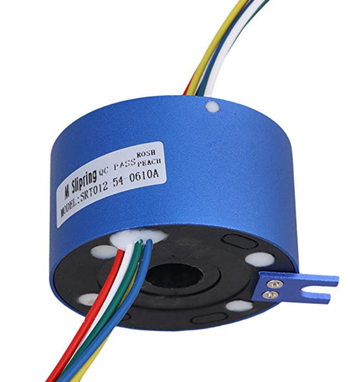
The rotor was then electrically coupled to the lower unit via slip ring.
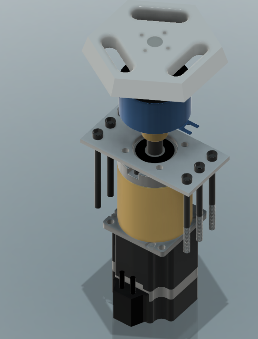
In addition to these components I made a 12 mm steel drive shaft extension and used it with a bore brass shaft coupler from. The purpose of this device is to couple the motor shaft to the extension shaft. The Slip ring was then added onto the extension shaft. Finally a rigid flange coupling motor guide was placed on top of the extension shaft, this made it possible for me to fit the hexagonal shaped drive piece onto the top of the shaft and couple the motor to the rotor. This final piece was 3d printed because of its unique shape and enabled me to drive the rotor.
Unfortunately the plastic is not very strong and the result is the rotor has about 5 degrees of wiggle back and forth. However this is a difficult problem to solve. I am hoping to fix this problem in the newer model that I plan on building. In addition I hope by selecting the high precision planetary gearbox motor will give me less wiggle on the motor than the economy planetary gearbox I used on the previous model.
Step 2: Drive the Motor
To drive the motor I have designed and assembled a few circuits based around the Trinamic Motor Control TMC2041 IC. This integrated chip simplifies the driving of stepper motors, making it possible to drive up to two motors from a single chip. This IC boasts a remarkable 1/256 micro stepping resolution. This gives the unit a remarkable step resolution that can be calculated as the steps per degree of the motor (1.8 degrees/57 gear ratio) then divide this quantity by the microstep resolution of 256. The resulting step resolution of the the current project is then 0.000150 degrees of 150 millionths of a degree. This extremely fine resolution gives rise to very smooth motor accelerations and further enhances the utility of your motors.
Step 3: Measure Accelerations and Read Direction
Unfortunately the current circuit does not allow for use of the rotary encoder built into the motor. As a result the device uses a motion sensor attached to the rotor to measure accelerations and read direction. Although it would be very useful to me to have an encoder, I can not free up enough GPIO pins to read all of the pins of the encoder.
With the new motor, which has 1:100 gear ratio the new design will achieve a 70 millionths of a degree resolution. This will be yet another improvement that will lead to smoother motor motion and more accurate performance.
Discussions
Become a Hackaday.io Member
Create an account to leave a comment. Already have an account? Log In.