 Sagar 001
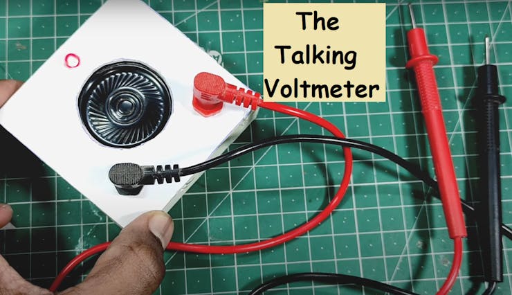
hello guys, today we are going to make a smart talking voltmeter. This one is built on Arduino and gives the reading by speaking itself. This function is cool and attractive because when we are working on circuits, we have to see again and again the readings and then switch the voltmeter leads to measure again the voltage. We will learn how to add supported libraries and where to get them, how talking function of Arduino works, how it reads the voltage and what changes should we have to do in order to increase the range and precision.
Note* For now we are considering a low voltage range from 0-5volts. Which is properly supported by Arduino. To measure high Voltages, we have to add a resistance voltage divider network and change the code accordingly the values of resistance. Every thing is mentioned in the code given below.
Components required:
1) Arduino Nano
2) Pam8403 (Class D amplifier)
3) 100k Resistor
4) Speaker
5) 100nf capacitors
6) Breadboard and wires
Circuit diagram:
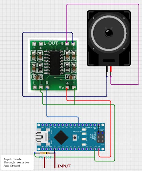
Circuit description:
We are using Arduino Nano in this project which is RISC AVR based 8-bit Microcontroller and here we are using talkie libraries to operate the audio functions. And a class D audio stereo 3W module(PAM8403) to amplify the signal for the speaker. There is a voltage in the digital pin of Arduino which is sensible by the code so a 100k- 1M (High value) resistor is used in parallel of the leads. There should be some voltage drop across the sensor so try to use a bigger value resistor.
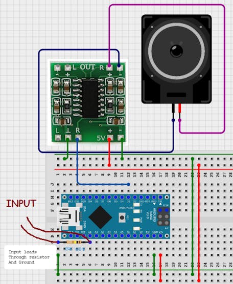
Breadboard schematics:
About Cirkit designer software:
Here is our new schematics designer tool “Cirkit Designer” which is totally free to all and is the most comprehensive breadboard layout tool.
Accordingly, I think Cirkit Designer is the best software to make breadboard schematics presentations. It also gives you the ability to view the circuit net diagram and BOM (bill of materials). This is very helpful for presenting yourself well as an electronics student or hobbyist, and the bill of materials helps to estimate project cost and procure parts.
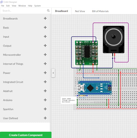
Cirkit Designer is a one-stop-shop desktop application for designing and documenting circuits and electronics projects. With Cirkit Designer, you can lay out realistic circuit diagrams that are linked to a bill-of-materials so that you can seamlessly order the parts to your circuit.
Download cirkit designer from Here
In the next release, Cirkit Designer is adding a code IDE with full support for compiling and programming Arduino boards, as well as a library of reference circuit designs (circuit templates including documentation, components and wiring, and code). Cirkit Designer will become the one-stop-shop to help you progress from concept to fully working breadboard prototypes. Simulation will also be added in the future, so that you can test your circuit before buying parts and building anything.
Code:
The code is separated in 3 different parts(2 supported files and one main file). You can Download full code for this project from HERE.
#include <Arduino.h>
#include <Talkie.h>
#include <TalkieUtils.h>
#include <Vocab_Special.h>

#if defined(__AVR__)

#include "ADCUtils.h" // for getVCCVoltage()

#elif defined(ARDUINO_ARCH_SAMD)

// On the Zero and others we switch explicitly to SerialUSB

#define Serial SerialUSB

#endif

#if defined(ESP32)

/*

 * Send serial info over Bluetooth

 * Use the Serial Bluetooth Terminal app and connect to ESP32_Talkie

 */

#include "BluetoothSerial.h"

BluetoothSerial SerialBT;

#define Serial SerialBT // redirect all Serial output to Bluetooth

#endif


/*

 * Voice PWM output pins for different ATmegas:

 *  ATmega328 (Uno and Nano): non inverted at pin 3, inverted at pin 11.

 *  ATmega2560: non inverted at pin 6, inverted at pin 7.

 *  ATmega32U4 (Leonardo): non inverted at pin 10, inverted at pin 9.

 *  ATmega32U4 (CircuitPlaygound): only non inverted at pin 5.

 *

 * As default both inverted and not inverted outputs...
Read more »
 adamc
adamc
 Lithium ION
 ober
ober
 Sander van de Bor