kelvinA
Navigation
The title tag system is explained here, and the table is updated when a change occurs. Notable logs have bold L# text.
| L1 [R] - One of my only unnamed project logs ever - Contains HSlice, a GCODE modifier and "Bread" | L2 [R] Craftware Pro - Includes a satisfying view change animation | L3 [A] Name Changes |
| L4 [T] UI and Licensing | L5 [R] Ease Of Use | L6 [A] Merging gd0096 into project |
| L7 [R] UX/Feature Research | L8 [M] Quick wireframes | L9 [T] split installer into separate project |
| L10 [R] Voxelizer 3 | L11 [T] Licencing | L12 [A] Splitting enSketchen [gd0096] |
| L13 [T] Lego compatible supports | L14 [T] Auto material calibration |


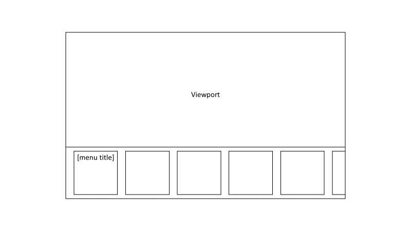
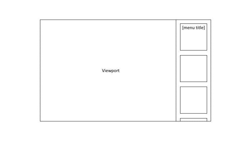 Obviously, some users may want the menu on the side of the screen and not the bottom. That is the reason I'm not updating to Windows 11 atm. Many users are moving towards ultra-widescreen. The first wireframe is geared towards users that like centered interfaces and the window (notice how I didn't say screen) has an aspect ratio of 16:9 and lower (lower = more square).
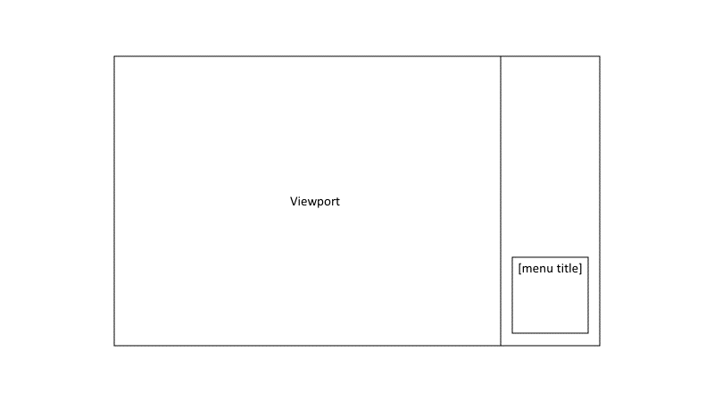 Mobile
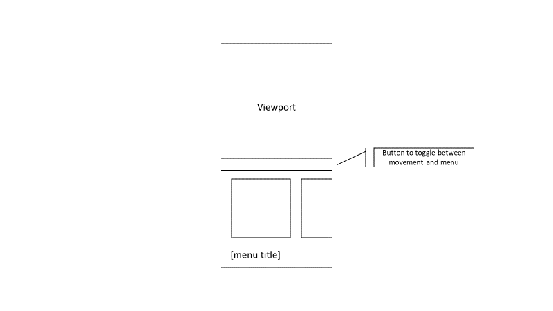 I don't want any UI elements too close to the bottom of the phone, as I've learned from using the Realme Q3 Pro with its ultra low fingerprint sensor is an undesirable idea. To make better use of space, the first card is removed and the menu's title is at the bottom. Overscroll will be in this menu too.
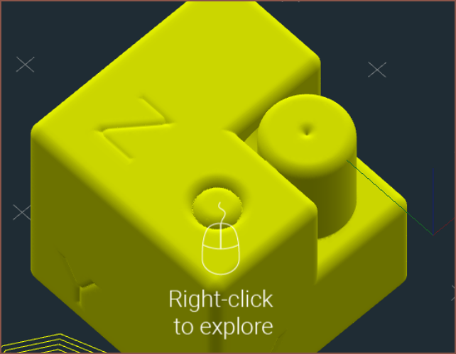
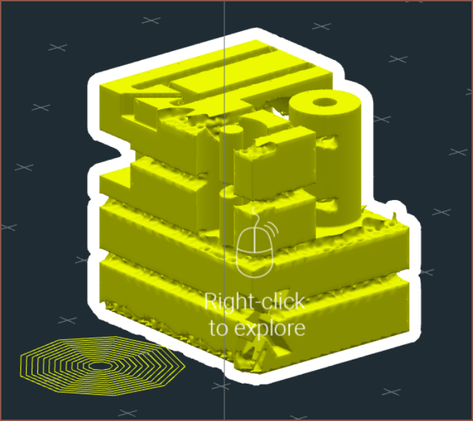
 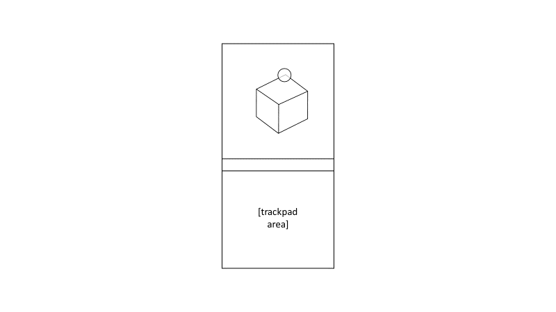 The circle is the user's orb cursor and locks to the closest thing in view. Then, when the user takes their thumb off the trackpad area, the view rotates for a better look of the corner.
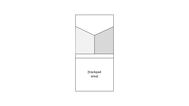 Conclusion
 Jenny List