Close
0%
0%

T^2 Tiles [gd0095]

If a competing company produced a home-use version of Aperture Laboratories Panels.

Public Chat
Similar projects worth following
Introducing the Technology Squared Tiles! Planned since the early days of 2020, this is a very large project with a very high price tag, planned to take a very long time to complete. Well, that mainly depends on how many tiles are being installed.

I say "competing company" to infer that I want it to move similar to the Apertue Panels, but with competitive features and design freedom

This project is planned to be printed on the SecSavr Suspense [gd0105].

Media

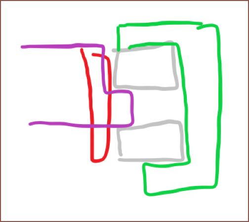
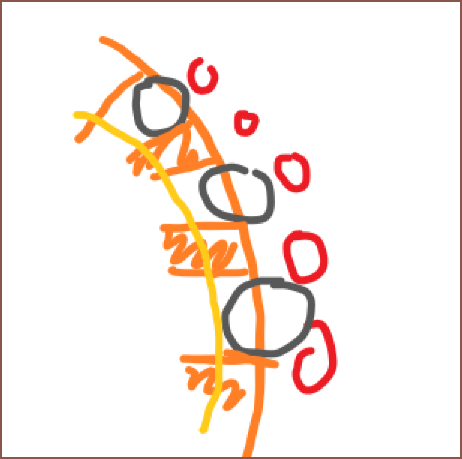
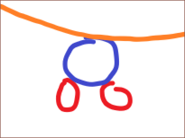
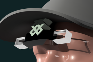
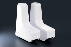
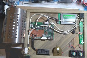
Inspiration and/or examples of working principle

Navigation

The title tag system is explained here, and the table is updated when a change occurs. Notable logs have bold L# text.

L1
[A] Project inspired by...
L2
[A] Project status
L3
[T] Installation location and material issues
L4
[T] 160x160mm Bevelled HUB75 and Glue On Board coating
L5
[A] Having to fully remodel
L6
[T] New Harmonic Drive Ideas
L7
[M] Hurdle hit for harmonic drive
L8
[M] New Strain Wave Reducer / Harmonic Drive
L9
[M] Moving to 192mm Tiles
L10
[R] Harmonic Drive Tweaks and Part Sourcing
L11
[M] Skeleton Model
L12
[A][R] 13:1 and Tooth Profile Research
L13
[T] String/thread for power transfer?
L14
[T] 192*192*64mm, Hydraulics and Slip Rings?

Preface

[2024 - Jan 14]

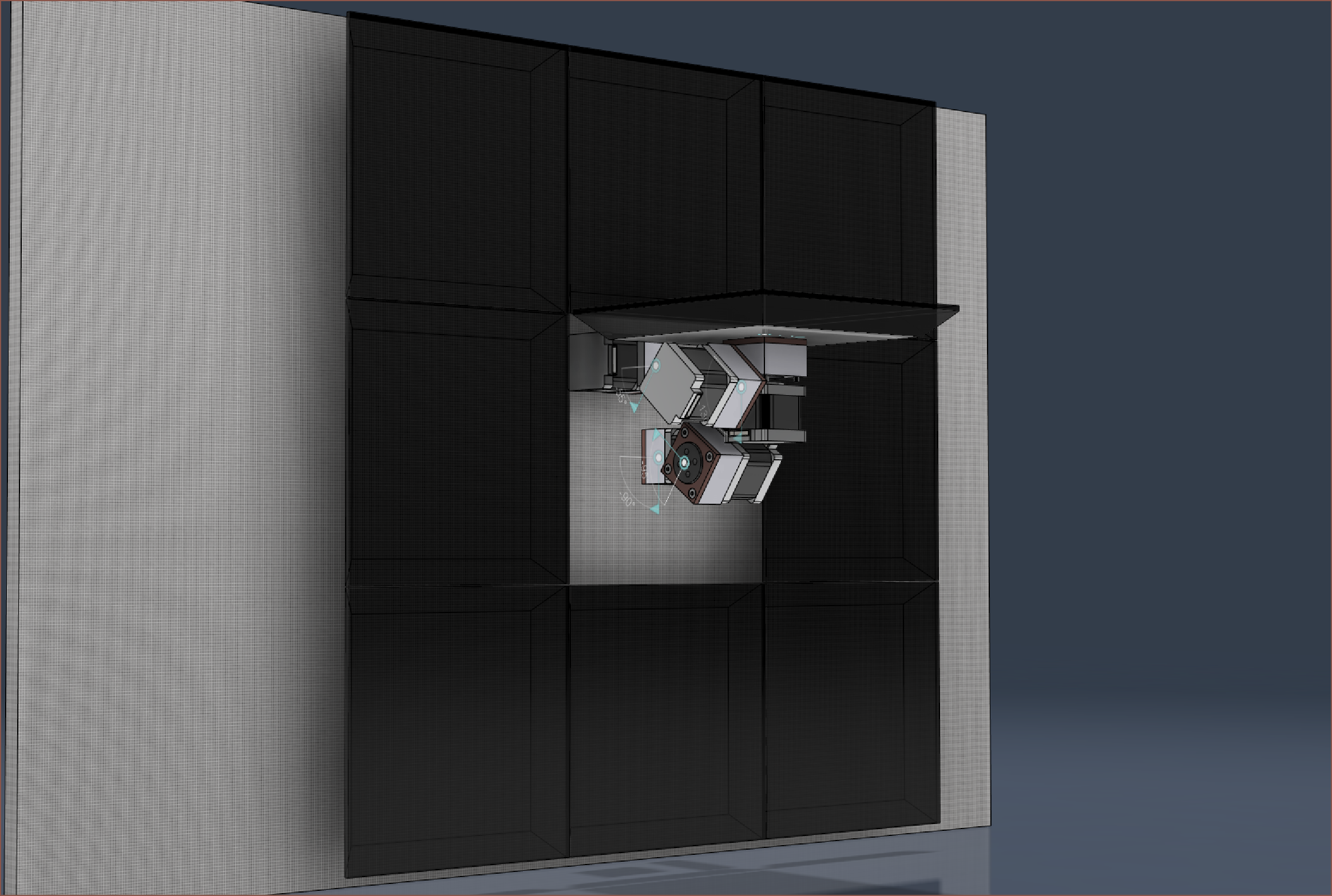
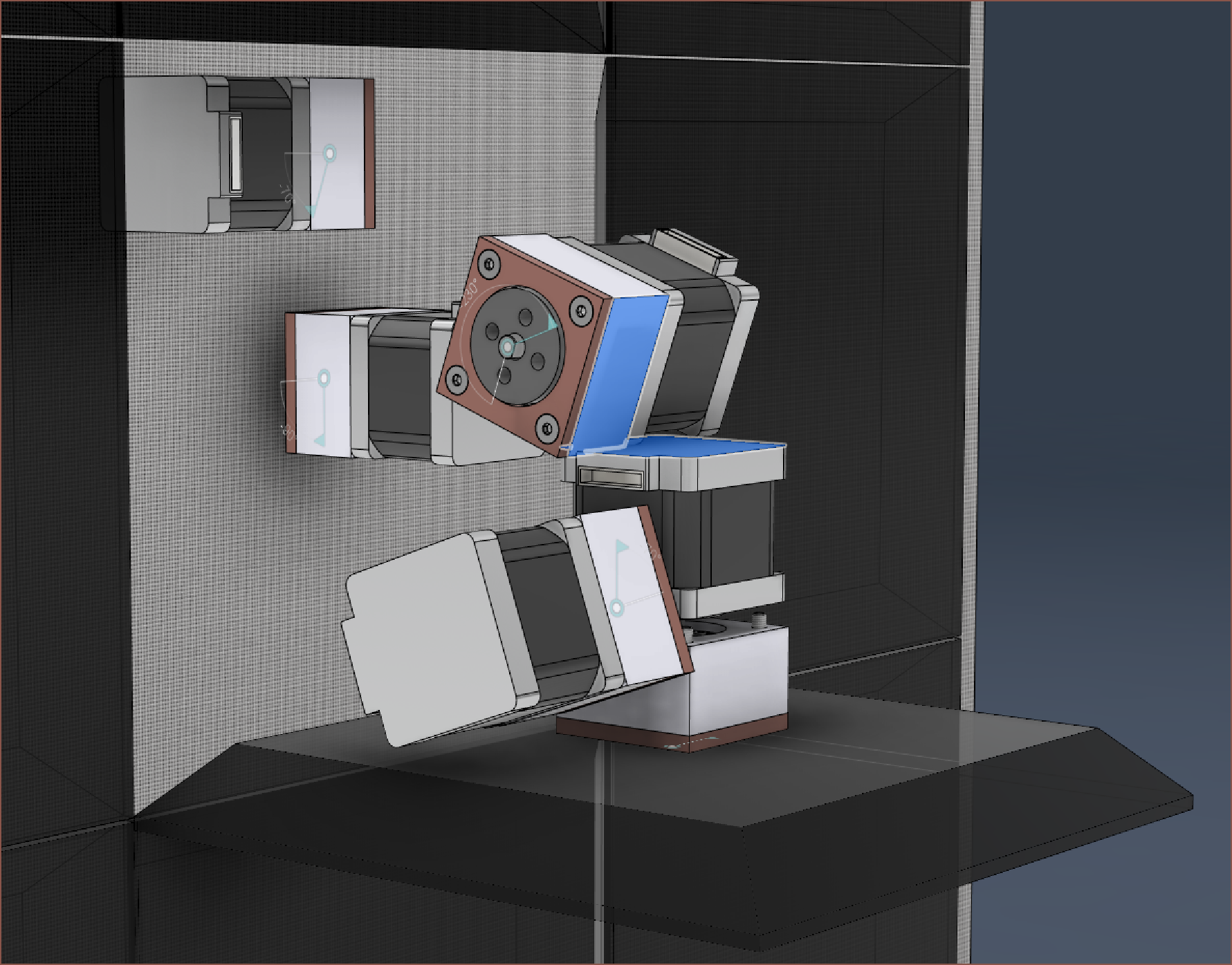
This project idea started in the first week of 2020 after YouTube recommended me a lot of Portal content, and I was imagining what it would look like if there was a consumer model of the approx 1 x 1 metre, 7 axis Aperture Science panels that was simpler, smaller and cheaper. Those 3 aforementioned adjectives are not really Aperture's style, so I was imagining how different brands would design it, similar to how laptops or fridges from different brands look different.

In terms of practicality, this project scores low. However, in terms of personal morale (basically company morale but I'm the only one in the company), it's very high.

This is supposed to be a long term project that is sufficiently large and cool enough to prevent any other random projects from cropping up, as well as making sure I'm thinking of the future when I'm working through the projects of today. For my LED animaition projects, the basic idea of scale is:

  • [T] 192*192*64mm, Hydraulics and Slip Rings?

    kelvinA06/04/2023 at 16:48 0 comments

    Getting 160*160*80mm total dimensions sounds juicy, but as I've mentioned before, the 192mm tiles are overal just a better option. Thinking about it, what sounds jucier is a solution that's even slimmer than 80mm, and 64 is a factor of 192.

    All 5 motos would have to be placed flat as, excluding the 18mm LED matrix and 1mm clearance gap, I'd only have 45mm of real estate. That's only 10mm more than the width of the motors themselves.


    I'm also thinking of using mineral oil, like in bike brakes, instead of fiber thread. I just imagine that the axes would be stiffer and more precise. In either case, I still have to worry about Axis1 and Axis5 since they have near or over 360 degree axis limits.


    That brings me to my next question; should I give in to the slip rings?

    It seems like they're an okayish size for an okayish price these days. Axis1 only really needs to travel 270 degrees, so the cable management shouldn't be an issue there, but after 3.5 years, I still haven't thought up a decent solution for Axis5. 

    The idea would be to send 36V power through 2 pins and data-in through 2 pins. Assuming 14 bits per channel, that should only be 1.23 MB of bandwidth required. Perhaps only 1 data pin would be necessary. On the LED matrix side, there'd be components to convert the 36V and data into 5v and HUB75.

  • [T] String/thread for power transfer?

    kelvinA06/01/2023 at 01:17 0 comments

    It may be 2am right now, but I'm still riding on this gd0095 motivation wave while I've still got it. I just found this video:

    I was like "Of course! I remember now!" because when I was idly thinking about "If I had to make a humanoid robot, what would I do?", I came to the conclusion of doing this method for many joints.

    Using string/thread could really help out with moving the center of mass away from the right end of the Tile arm and allow me to move with lower torque requirements, higher accelerations and lower unwanted displacements. Because I like stuff that's exotic, I'm thinking of using basalt thread for this task, though braided kevlar rope would probably do the job fine too.

    The only issue is that the bowdens now are under the same issue as the main thing I was worried about: Wire Management. Wait. If I mount all the motors to Axis1, I think it will actually be fine.

  • [A][R] 13:1 and Tooth Profile Research

    kelvinA05/31/2023 at 23:34 0 comments

    I was looking at harmonic drives on AliExpress (to see how my £4 hypothetical solution measured up) and I've just realised that I've actually modelled a 13:1 reduction, not 14:1 as intended. I'd need efficiencies of >77% to obtain 10x torque. I've also remembered that the actual torque of Nema motors usually peak at 75% their rated torque (e.g. you only get 0.9Nm from a 1.2Nm Nema23). so even if I did get the 10x torque, I might only have 1.425Nm to work with. 

    202mm is the maximum that the 192mm tile can extend out linearly.

    Assuming I use a 148mm arm, and also assuming that it center of mass when fully extended (see below) is 200mm, I only have 727gf. Oh, I don't have to assume where the center of mass is, at least by just going off the 3 motors.

    It's 173mm away, which equates to 840gf. Remember, that doesn't include a lot of other components that could push it out further.

    Each motor is 175g on its own and the harmonic gearbox is likely 25g or more, so I'm already down like 600gf ish.


    I've also looked into the pile of papers that exist for harmonic drive reducers, and I found this interesting part of one:

    Study on tooth profile design of harmonic drive with deformation model of flexspline

    The teeth actually look rather cylindrical, no? I can also see that the actual mesh angle is rather steep actually, further implying that I should try to keep that angle under 30 degrees. If I changed the design for a 14:1, I'd get a 35 degree angle. I could always change the flexspline pins for 1mm pins and get a mighty steep 10 degree angle though.

    1.5mm pins
    1mm pins

    Lastly, I remembered that the difference between the major and minor axis of the elipse required will be different at the wave generator compared to right at the pins. Think of doing an offset on a rectangle (see below). The inside rectangle is much narrower than the outside one. The same thing happens for the wave generator, and it was 0.6mm short. That doesn't sound like much, but it's like 0.3mm each side, which is 20% the diameter of a pin.

  • [M] Skeleton Model

    kelvinA05/31/2023 at 19:49 0 comments

    Unlike the first time, where I modelled axis 1 through 5 almost to a "render ready" state, I've just jointed motors to motors with air holding the model together. You're going to have to imagine that there are beams in the middle.

    I wanted to see if I could get a 160x160x80mm solution, and i was so close but there's an intersection on the corner of Axis 3's motor when in this specific pose. I was planning on only mounting Axis 5 with 2 screws instead of 4, hoping that the ouput part of the harmonic drive will be strong enough for the job:

    I stretched the arms to the maximum allowable length, which was 114mm, and it seemed like I was going to get away with it too.

    I was hoping that I could use the lighter tile and shorter arm lengths to my advantage to have faster animations at the end of the day, but it does look like 160mm is just a tad too small and I will have to go to the P3 panels. 

  • [R] Harmonic Drive Tweaks and Part Sourcing

    kelvinA05/31/2023 at 12:05 0 comments

    The pins are the most expensive part of the harmonic drive and if I'm going for 16 Tiles, I need 4320 of them, so I got to looking if I could find them cheaper. I found this:

    Price for 1000pcs, excl VAT

    These are needle-roller-bearing pins that have a diameter accuracy of +0/-0.01mm. This seller also has any integer length from 3 - 20mm, so if I need a certain size for the gearbox, I can have it. I just would like to either keep the same size for all of them or, if I must use two lengths, the actual lengths are noticably different. I don't want to be trying to discern the difference of hundreds of 9mm and 11mm pins.


    Running mental life-cycle simulations, that wave generator + steel BB proposed solution was still failing and I knew I had to change it out. Conviniently, while I was out searching for the pins above, I found out that you can actually get ball bearings in POM. In another listing, their balls are advertised to have a +/- 0.01mm tolerance and that they're self-lubricating.

    Price for 1000pcs, excl VAT

    There's probably a reason why V-Slot 3D printers, even the high-end ones, don't use metal wheels, and I heard that it's because they have the potential to damage aluminum extrusions. A small, 3D printed part has an even lower chance of survival.


    Now that the ball is down from 4.5mm to 3.175mm, I wanted to reduce the height by 1mm. I also found out that the Nema14's I modelled were actually 2mm longer than the real world ones. 

    Anyway, the only way to do that was to reduce the distance between the bearings to 2mm. It was for the best, though, since that lip for the output is only held by 28x 0.8mm walls (reinforced by the pins) and so a taller lip could buckle easier. I'm also not expecting extreme forces to be pushing or pulling on the output, and axial loads are transfered to the pins. Now, the pin rests on the entire 4mm of the top bearing (instead of 3mm previously), further distributing the load on the output printed part. The minimum thickness of the wave generator is also thicker now.

    I've also modelled the actual balls, and it's looking like 8-10 with a cage or 12 balls without will fit. I'm also wondering if I should remove the brass inserts and instead tap in the screws for the wave generator. Looking at the videos below, probably not unless I've done some actual testing.

    I wanted to see what others were doing about this, and so I started looking at other 3D printed harmonic gearboxes and found these:

    • Used dual screws to hold the wave generator on the shaft.
    • The wave generator slipping on the motor shaft was the main point of failure. It could be seen that he tried a square nut first that broke the pocket it was in, but after that he was just doing "some changes" to improve it and I couldn't see what.
    • The flexspline delaminated. I shouldn't need to worry about that since I'm using "bearing steel" pins.
    • At max force failure, the flexspline split in half.

    Instead of removing the brass inserts, I'm going to double trouble and use 4 of them:

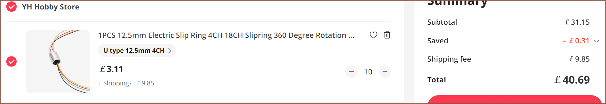
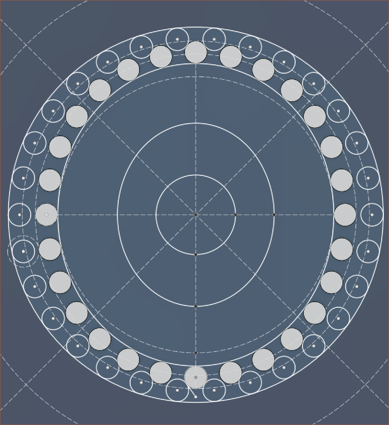
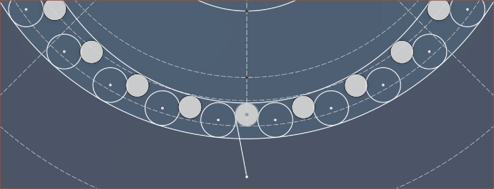
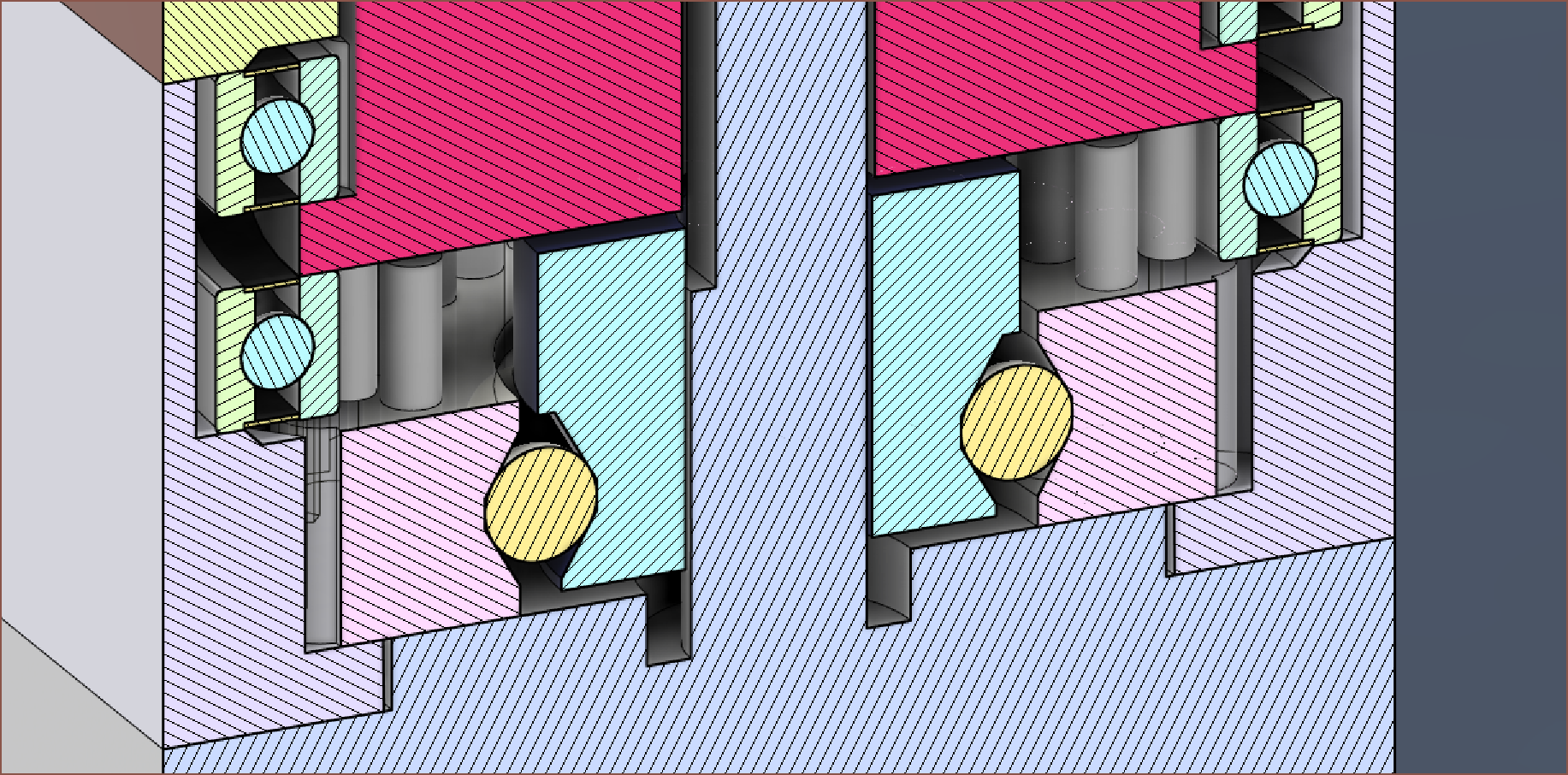
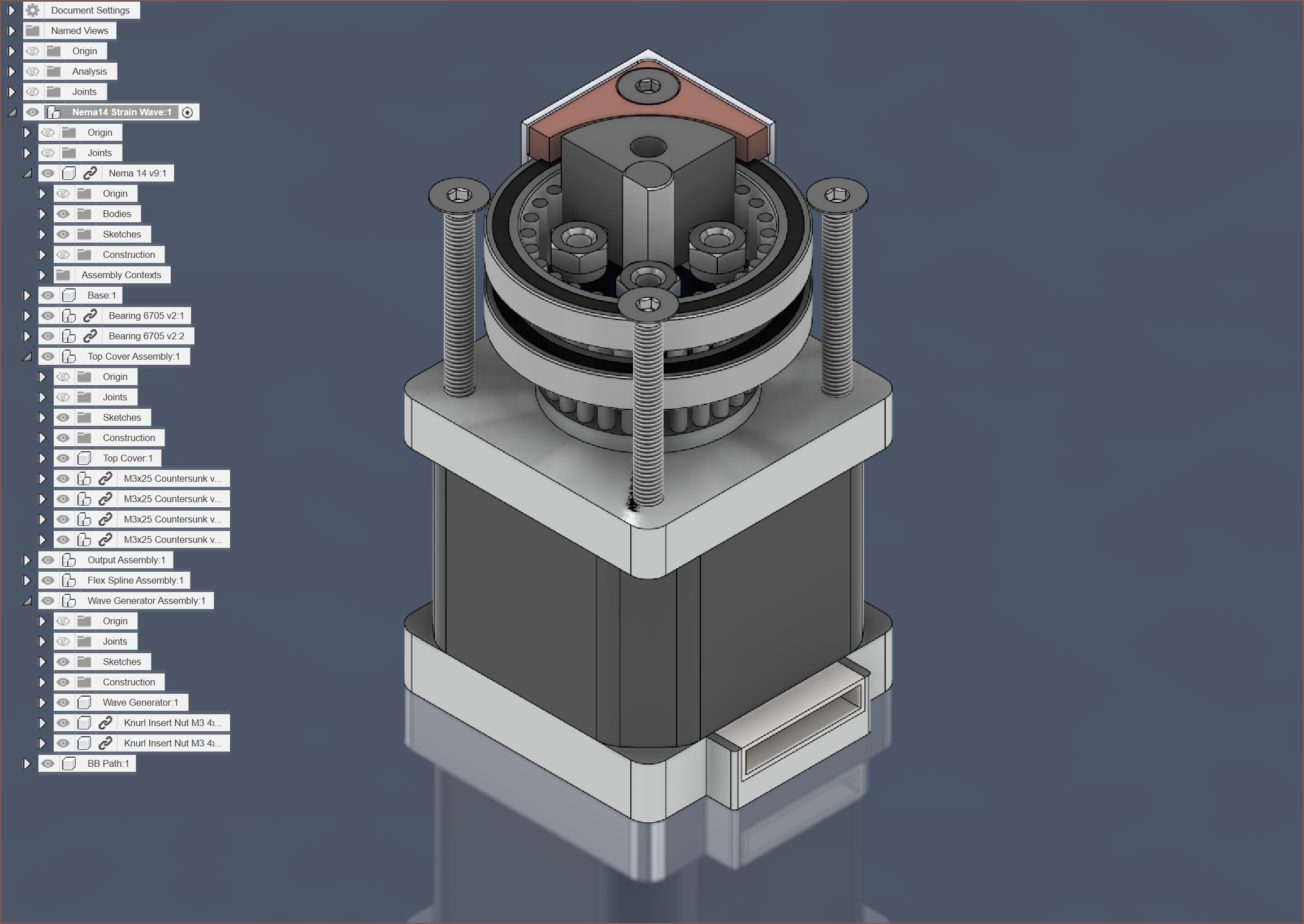
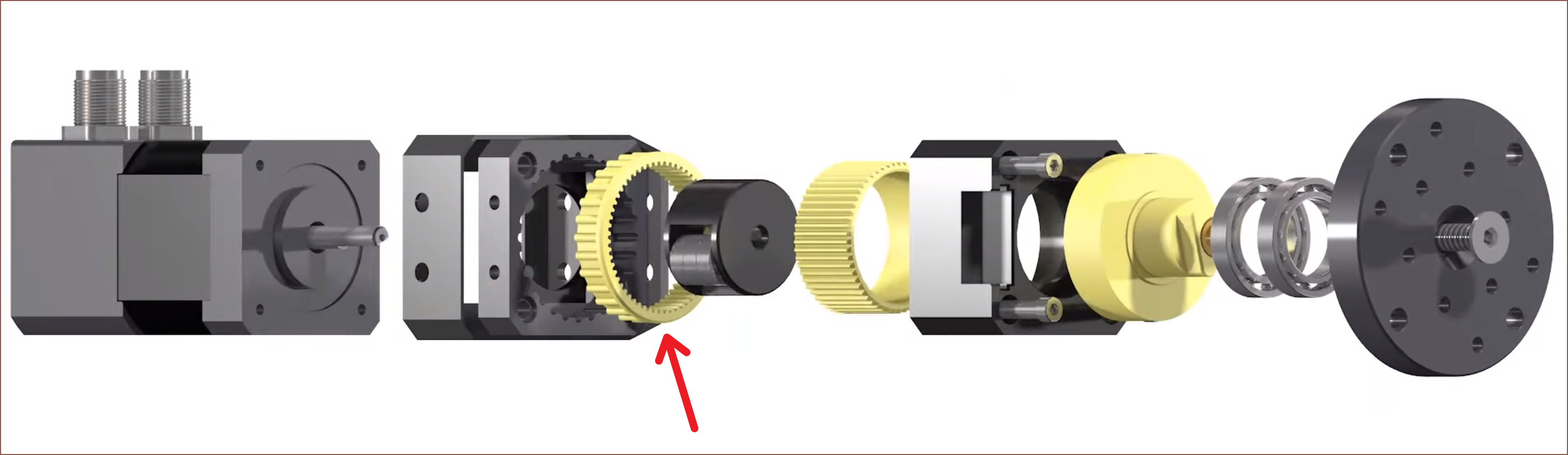
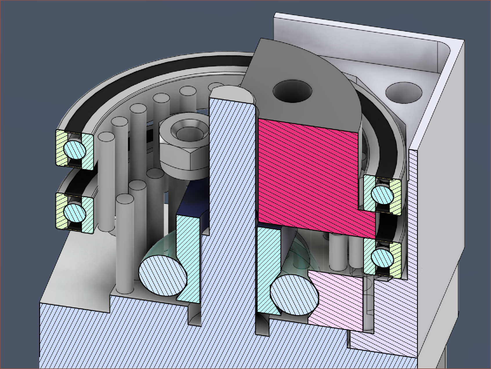
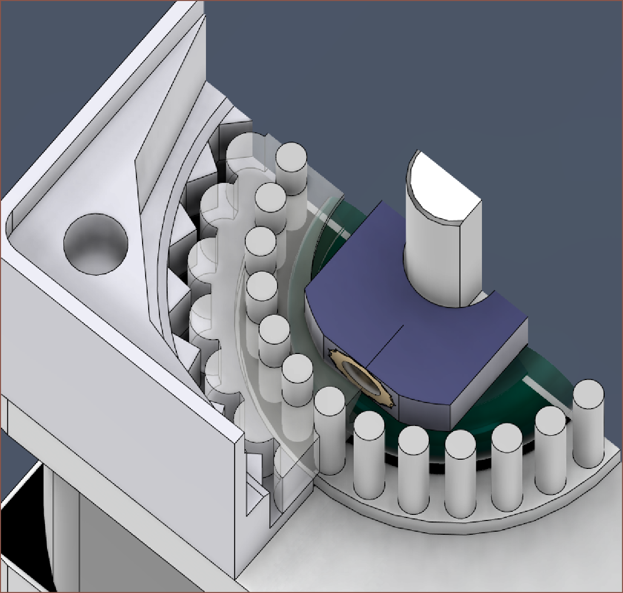
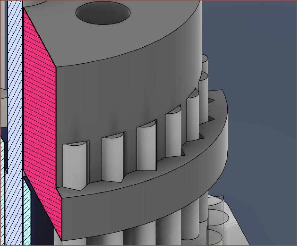
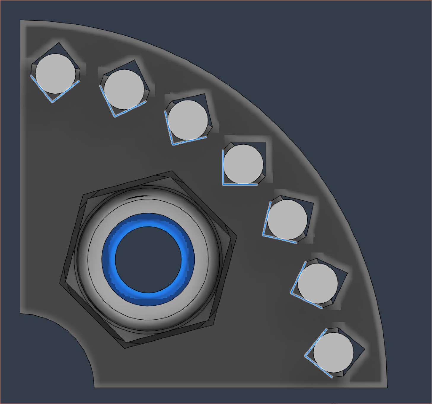
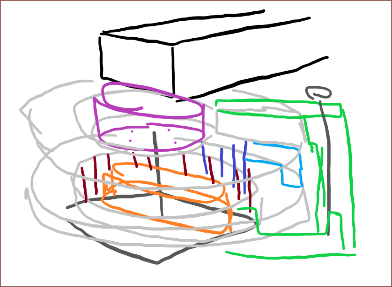
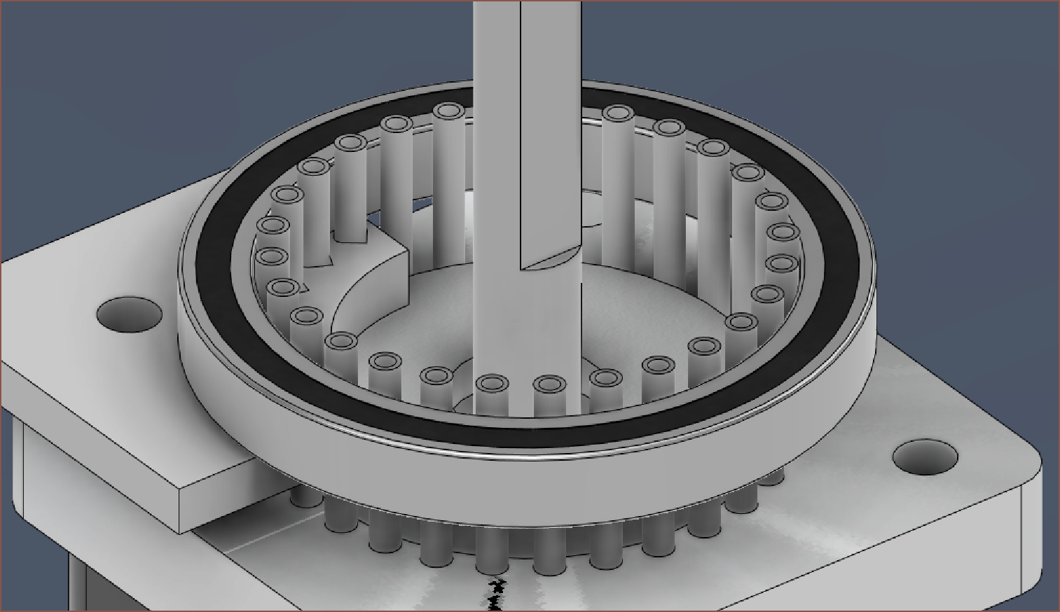
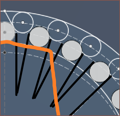
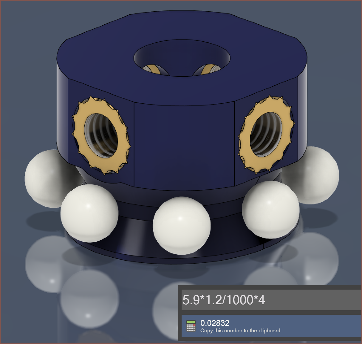
    Speaking of 4, I think I'm going to pass on the cage and instead use 12 balls. The difference would be 3p, and I'd expect that a 3D printed cage would cost more. Additionally, more balls means that the loads exerted on the wave generator are more distributed and would better imprint the eliptical shape onto the flexspline.

  • [M] Moving to 192mm Tiles

    kelvinA05/30/2023 at 13:26 0 comments

    I've made the Nema14 a cylindrical joint (with limits), and I can barely get an extra 15mm of spacing needed for M3x40 countersunk screws whilst still being able to affix the wave generator to the shaft. Now I've done that 4th-to-5th axis idea and it's cutting it close:

    Wough I'm just cutting it close all the way down. I'm only a handfull of millimetres from the new target of 160mm:

    Sketching in the other axes, it seems that I can get a 110mm long A2-A3 arm (and the A3-A4 would be half that, at 55mm) and I could stretch that to 112mm. This means that the maximum extension is 165-168mm, barely longer than the LCD panel. I was hoping that I could do this all under 100mm, but the laws of geometry isn't going to let that 5th axis slide:

    I would have enough space for a 192mm P3 panel though, with an A2-A3 arm length of <=146mm and full extension of 219mm:

    For the 160, the max load is under 1.175kgf and for the 192, it's 0.885kgf if I'm able to get the 10x torque increase on the 0.19Nm motors and assuming the center of mass is at the full extension point. 1200g and 900g seem like ballpark figures, and 160x160x140mm or 192x192x96mm sounds like. I think I'll go 192.

    As it turns out, there are both flat and bevelled versions of the LED panel in 192mm size, with identical prices:

    The price difference is £5 and I can reliably get 1kg of material for £10, so unless a printed frame would weigh about 500g, it might be cheaper and more beneficial to go with the cheaper traditional panel. 

    Another benefit from the P3 panels is that the power header isn't right in the middle of the panel where Axis5 needs to be mounted:

    It's sounding like 192mm has all the benefits and none of the drawbacks. I get more wall coverage for essentially the same price, and the thickness difference is not something to pass on.

  • [E1][M] New Strain Wave Reducer / Harmonic Drive

    kelvinA05/29/2023 at 20:56 0 comments

    Right so it's been... checks notes... 36 hours since I wrote the log saying I don't know how to progress further. I've now essentially finished modelling the entire thing, and it should be smaller, better, faster and stronger than the previous harmonic drive I designed but never tried out. I've got more confidence in this one, which is now only a compact 35*35*24mm.

    I've gone for the strategy of having a solid output assemby and input flexspline, taking inspiration from this satisfyingly animated video.

    Namely, the part marked with the red arrow:

    This is a section view of the design:

    • Transparent Green: 4.5mm Steel BB path
      • I wanted to use plastic to reduce the likelihood of raceway damage, but it only comes in 5.95mm sizes.
    • Dark Blue: Wave Generator with the choice of 1x or 2x M3x3 heat inserts. 
    • Transparent: Flexspline
    • Dark Grey: Output with 4x M3 self-locking nuts in a 9.5mm*9.5mm square
    • White: Enclosure
    • Bearings: 2x 6705-2RS 25*37*4mm
    • Pins: 54x solid 1.5mm*10mm stainless steel. I found a seller that offered them for 30% less than the steel tubes I found.
    • Copper (not shown): Top cover plate + 4x M3*25mm countersunk screws

    To stop the flexspline from spinning in place, I've gone for 2.5mm cylinders that fit into 80 degree V cutouts:

    Instead of a circle, I've used a decagon for the bearing-to-enclosure press-fit to allow for higher print tolerances.

    Here is the raceway profile I've used for the flexspline and wave generator, where the ball is in contact at 3 points on each side:

    I just need to model the bearing spacer, which reduces both the amount of bearings needed and the friction of the bearing. It looks like the grey component below (click image for source), where the red component in the image would correspond to the wave generator:

    Speaking of that wave generator, I'm cutting things close. 4.5mm BBs are cheaper than smaller sizes like 3mm, so I looked to see if I could get away with it. The wave generator is only a 1.2mm wall at it's thinnest cross section. Hopefully, the 5mm motor shaft will reinforce this part.

    The pins also act as a precise metal-on-metal contact between the output and the bearings. Unlike the flexspline that uses circular pin holes for a tight fit, the output uses more V's (these are 90 degrees) so that the pins shouldn't be overconstrained:

    I'm using self-locking M3's because I've got the space and all this stuff is moving. shaking and vibrating so it's probably for the best.

    In terms of pricing, all the metal components total to £3.69/ea, assuming rates of 

    • 1500 BBs for £7, 
    • 700 pins for £16.05*, 
    • 10 bearings for £6.96*, 
    • 250 brass inserts for £4.75*, 
    • 100 M3 self-locking nuts for £5.20,
    • 50 M3*3mm grub screws for  £0.83*
    • and 100 M3*25 countersunk screws for £6.37. 
    • (*used [£price]* 1.2 in the calculation to reflect the 20% VAT charge of AliExpress imports)

    It is also assumed that only 6 BBs and 1 heat insert + grub is used, thought I can imagine 2 would be needed to prevent vibrations due to the centre of mass of the wave generator. I think being able to keep the original idea of metal-on-metal contact for the flexspline-to-output transfer is the best part of this proposed solution, but the steel pins are the largest contributors to the cost. Add in the printed parts, and it's probably a £4/ea gearbox. Sure it's a 35*35*24mm, metal contact gearbox, but I was hoping for something like £2-2.50, with £3 as a stretch. I need 5 of these per Tile, so that means that I'm already at £37.50/ea from just the P2.5 LED Display and gearboxes (though, the seller has a near identical, non-bevelled frame display for £5 less, so I wonder if I could get even more savings by asking to buy a frameless version). The motors and S6609 stepper drivers are another £20.35 to the BOM/ea. 

    It doesn't look like 16pcs for £1000 is going to materialise...

    Read more »

  • [M] Hurdle hit for harmonic drive

    kelvinA05/28/2023 at 11:49 0 comments

    Yesterday, I was thinking "I know how to model this" and started researching and modelling the new harmonic drive and looking for the components I want to use. I thought 14:1 was a good reduction, and it's coincidental because if I can get over 70% efficiency, I'd get a 10X multiplier of torque. 

    It then kind of turned into a goal to:

    1. Only use the same amount of tubes as the amount of teeth a traditional harmonic drive would use.
      1. That means 28 + 26 = 54 tubes, as opposed to the 3D printed designs (mine included) that had both input, flexspline and output teeth. This would be 28 + 26 + 26 = 80 tubes.
    2. Get as many of the high wear or precision contacts to be metal-on-metal as possible. If this is not possible, see if UHMW tape can be applied to the surface.
    3. Only use 2 deep-groove ball bearings.
    4. Ensure flex-spline durability.

    Part of these goals were because I did some planning and thought that I could obtain a solution where the tubes slid over a single, solid wave generator:

    Here, I was going for a tube-to-tube angle of 30 degrees (which is 60 degrees if you thing of the entire V angle) or less so that there was more resistance to torsional loads. This just so happened to be just-about 25mm, which is an available deep-groove ball bearing inner diameter.

    I was still kind of clueless as to how I was going to actually model the design, so I drew up a sketch:

    Now, knowing how I needed to model, I started, taking advantages of the coincidence that the Nema14 bump is 22mm, the tube is 1.5mm and the inner diameter of the 6705-2RS is 25mm.

    This is where I've been for hours now, because I'm mentally doing simulations and one thing or another isn't working out.

    • My original flex idea was actually having these tubes tilted in like a cone, because it'll be easiest to flex while still having low displacement at the rigid end.
      • (Those grey lines should be purple)
      • However, the input tube-teeth are straight, so would slightly diverge away. Perhaps that's fine if the slope angle is low?

    • Then I was thinking of something similar to my first design, but I have to assume that the tubes are rigid bodies and so may not be able to properly interface with either the input of output tube-teeth. Even if that was the case, I'd need to use BB-balls / loose ball bearings like the orange one in a video in the previous log.
      • I'd likely use plastic as metal balls are likely to wear down the printed tracks.
    • I thought of having the output being completely rigid and with 28 teeth. Then, the flexing needed to take place on the bottom half and I don't have an idea how to fix it in place.
      • The idea was to be able to have a very rigid and aligned output shaft as the tubes could contact the internal bearing rings.
    • I considered something spring-loaded, but springs don't have an infinite fatigue strength and I'd likely introduce backlash into the system. 3D printed compliant springs probably wouldn't last either... not at the size I need anyway.
    • I also considered something similar where balls or tubes are pushed into place when needed and then are free to roll over the tubes when not, almost like some kind of piston x kinematic mount.
      • I guess a slightly more detailed sketch would look like this:

      • The tubes/pins/balls are pushed into the output-tubes when required, but are free to move out of the way when not. Instead of the flexspline requiring the restorative force, the output teeth are also the restorative force.

      • I think a tube or pin would work better than a ball, especially a pin with rounded corners to prevent binding.

      • Ideally, the tube/pin would be fully defined:

      • I think the issue with this one is going to be wall thickness of these small pathways?

      • It's most similar to a heliocentric gearbox:

    I'll have to do more thinking. I'm both trying to figure out what won't work just as much as what does, because that makes all mental simulations more accurate. 

  • [T] New Harmonic Drive Ideas

    kelvinA05/25/2023 at 15:43 0 comments

    Looking at the current file, the Tile sticks out of the wall by 140mm. I think it's possible to reduce this to under 100mm. To do this, I need to design an even smaller harmonic drive, yet with high durability, low load displacement (high torsional rigidity) and high torque efficiency. I'm going to take some ideas seen in the below videos, as well as the findings I've found in the past.

    For starters, I'm making all contacts metal-on-metal, looking at the pro gearbox in [Video 1]. The contacts between gears is the main part that requires the lowest tolerances, lowest friction and highest durability. "How are you going to fabricate that?", you may ask? Well, you know how the cyclodial drive in [Video 3] was made with steel dowel pins? While working on #Tetrinsic [gd0041], I found some ultra precise stainless steel tubes that come in 8mm or 10mm lengths that I plan to use as the teeth. This type of gear is called a "Lantern Pinion".

    The gearbox needs to fit in a 40 x 40 x 25mm volume. 25mm is the height that the shaft of the Nema14 motors I have extends past the mounting face. Ideally, the height of the gearbox would be 20mm. As seen in [Video 1] and [Video 2], I'll be moving away from deep-groove ball bearings and instead be using loose ball bearings for the wave generator.

    I'm wondering why spur gears are used instead of helical gears, looking at [Video 5]. Perhaps it's because the teeth hop from one position to the next? It could just be that it's harder to traditionally manufacture the metal harmonic gears. Another hypothesis could be that the straight tooth profile reduces displacement when a load is exerted.

    I'm also wondering why a 3-contact-point wave generator is seldom used. I can only imagine it's because one would need more teeth to get the same reduction, as well as increasing the amount of contact points, hence friction.

    Turns out ScienceDirect has a stack of papers related to the optimisation of "strain wave gear" and "harmonic drive", so perhaps the answers are somewhere in there... or not as I just skimmed though some and they're all essentially just optimizations.

  • [A] Having to fully remodel

    kelvinA05/24/2023 at 22:42 0 comments

    I'm inside the Fusion360 model, and while I think it's possible... there are so many changes required that I'd essentially have to remodel from scratch. 

    I'd also need to look into reducing the gearboxes, as well as ensuring that they have the torque efficiency I need. I think there have been a few videos testing harmonic drives since I designed the untested one way back in 2020, such as this one 5 months ago:

    If I recall correctly, I'm looking for a torque increase of about 15 - 20x. This was for the larger 256mm tiles though. Now it's 160mm and I'd like to also have an inter-tile gap size of under 2mm (instead of 9mm in the current file). This should mean that the torque requirements are slightly reduced. The video above shows that both gearboxes increased the torque 16x with a reduction of 25, thus 64% efficient.

    Then I've got to think of the main rotational axis. I could keep the 3D-printer-V-wheel solution, but I'm also thinking that I should eliminate the requirement for a fixed frame and make the Tiles act more like Nanoleaf's. This would require the Tile to be self supporting, and a large metal bearing could do that. Obviously, ball bearings will be too expensive:

    For a bearing this large, it may be possible to just use a single bearing, but these kinds of bearings are designed such that you'd either need 2 of these or this kind of bearing along with a thrust bearing. For both a cheaper and lighter solution, a lasy suzan bearing is likely the better choice:

    This is £8.07 on average.

    My concern is that these are primarily used in turntables, where it matters a lot less if there's a bit of backlash. I'm also reading this forum that discusses (robotic) applications for lazy susans and they're rather subpar; ok for turrets, not for arms. What I really want is a slew bearing, but haahahahaahahaahahaaha £156/ea = 360nopescope:

    As you may be able to guess, these Tiles are less of a "can it be done?" and more of a "how much will it cost to be done?" problem.

    Back to the wheels, they might be better for another reason: actuating the first axis similar to this:

    Actually, I might just try plain bearings since I've got 200 of them from the scrapped #SecSavr Sublime [gd0036] project. In an ideal solution, they'd be dual-ball bearings, but I just have ultracheap normal ones. I would need some way of preventing the entire thing from sliding out. Perhaps a thrust bearing could be used? There's also a "sandwich" described on the aforementioned forum:

View all 14 project logs

Enjoy this project?

Share

Discussions

Similar Projects

Does this project spark your interest?

Become a member to follow this project and never miss any updates