 kelvinA
Published: 15:34, Tues 24th May
Yesterday, I saw these two videos:
I thought it was intriguing and recreated it in Fusion360, and then thought about how I would do it in enSketchen only with the hardest device being targetted: the full-Android smartwatch. These watches are on China for between £30 and £160 depending on features and popularity, and I've used them as my main cellular Android device for years. I still much prefer square/rectangular ones to circular ones as I can get more done on them, but I'll explore to see if an interface can be made for both.
Designing for a smartwatch screen both helps to highlight how many clicks somebody on a PC or phone might need to take to produce a part, as well as having a workable user interface for split screen on phone and a really small window on PC.
Smartwatch
The idea is to have 4 digital buttons in the corners for an experience similar to Casio digital watches. These buttons can be held to activate a second function. Using draw.io, this is what I've got so far:
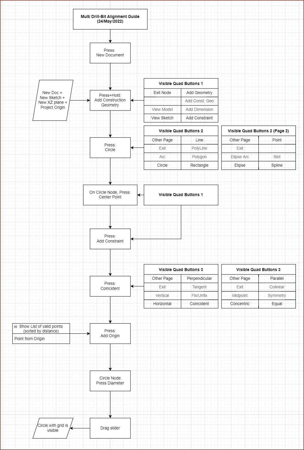
- We start by clicking "new document".
- The user's start template is loaded in. In this case, it's creating a Sketch Node with the initial Plane Node set to XZ and a Project Node follows afterwards that projects [ 0, 0, 0].
- The user can easily select "XZ" to open up a dropdown that shows the other 2 plane options.
- All nodes are placed in like a "master grid" to keep everything automatically tidy and easily navigatable.
- At this moment, the user is in a sketch and the 4 side buttons are to exit the Sketch Node, add geometry (like lines and circles), go to a view mode where the user can see the current status of the sketch and add a constraint, all in their respective positions.
- If you press and hold, the grey text part of the table applies.
- I'll probably set Other Page to the top left and have "Exit Node" be a press+hold, because the user needs to be able to do other things like create another plane in the sketch node.
- "Other Page" loops though all the pages, similar to a digital watch.
- The user then clicks to go into the construction geometry menu and then a circle, which places a Circle Node after the Project Node. Defaults are a 1mm diameter circle at the centre of the user's view. Since they haven't moved around in the sketch view yet, this center is [0, 0].
- The user then clicks the "Center Point" input, "Add Constraint" and "Coincident". A list of valid things to coincident are sorted in a list by how close they are, meaning that if the user doesn't see it/know which object they want, they can exit the menu and move the object closer and then come back to see if its higher up on the list.
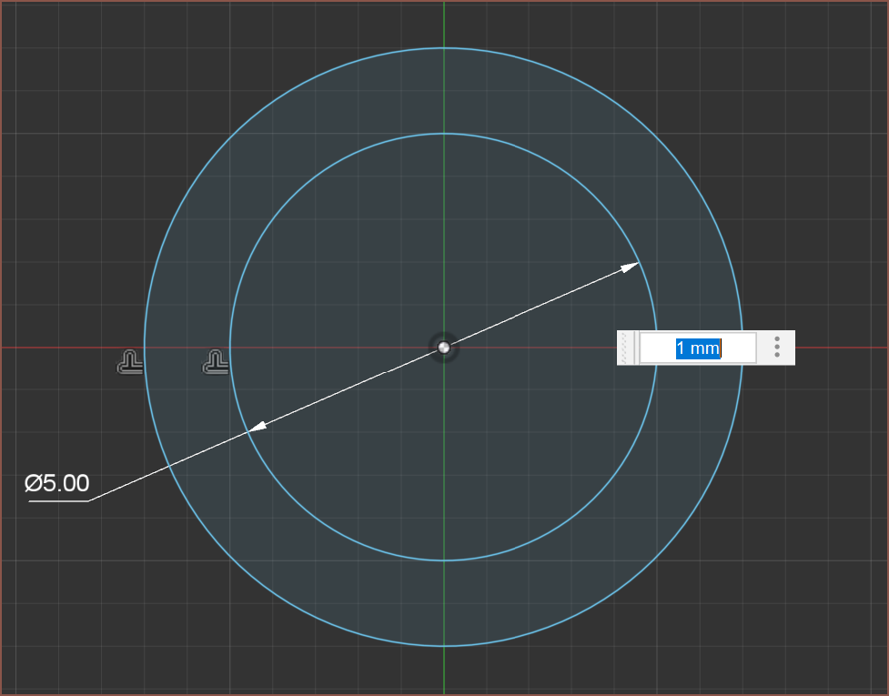
- So now there's a coincident node added and then the user clicks the "Diameter" input, hold for maybe 0.5s and then can slide their finger left and right to increase or decrease the value. At the same time, the circle is visible with a sketch grid (sparcely numbered) so that the user gets visual feedback on how big or small the circle is.
Normal Lines
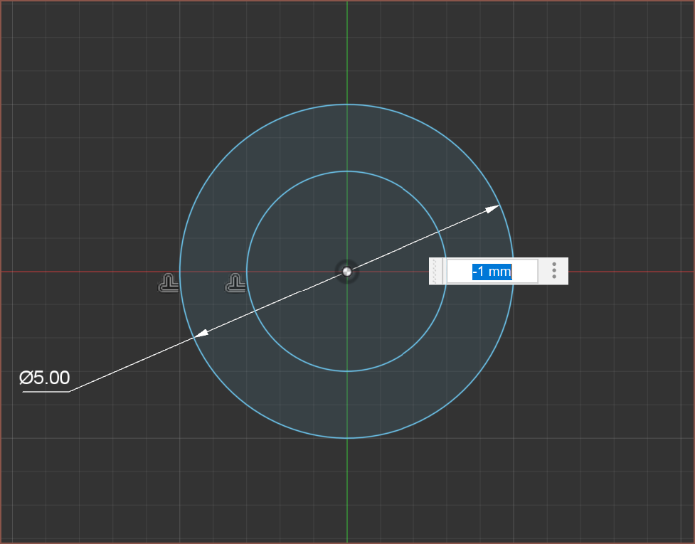
Additionally, like planes, I would like lines to have a normal line, meaning that dimensions are usually signed. Think of it similar to dimensioning an offset in Fusion 360 where a positive dimension is one side and a negative dimension is the other side. The behaviour can be changed on a per line basis. I want to implement this feature in hopes of getting a fully constrained, no other solutions sketch.
I'm sure users of Fusion 360 have experienced when a dimension, line or arc has swapped sides. There are many cases were a fully constrained sketch could still have 2 or 3 solutions depending on location of the sketch elements.
This approach also allows to do the following:
- Imagine 2 concentric circles of different sizes.
- Now if you click on the circumference of the larger of the two, and then the smaller, create a dimension.
- Enter 1mm as the dimension.
- The smaller of the 2 will now have a diameter that is 2mm larger than what was previously the larger circle. The first circle selected would not have changed size
- This is because I have defined negative dimensions as inside circles and positive dimensions as outside.
- In Fusion360, you would have to first drag the smaller circle until it was larger than the largest one before dimensioning it.
Some images of the Fusion 360 Offset tool, which may help convey my idea:
 For arcs, perhaps the software would ask if you want a 180 degree or a 0 degree tangent.
Conclusion
I'm coming up with a bunch of workflow pathways faster than I can add them into the flowchart, so I'm likely going to be doing more over the coming days to explore the UX and workflow. If I can get some half decent speed on a smartwatch, all other platforms should feel resistanceless.
Discussions
Become a Hackaday.io Member
Create an account to leave a comment. Already have an account? Log In.