 Sam Ettinger
In my last project, I used a 1.5mm ATtiny20 to make a 5mm LED that can run arbitrary patterns. It's a delight, and someone should put me in touch with Id Software so we can release a series of licensed Quake flicker LEDs.
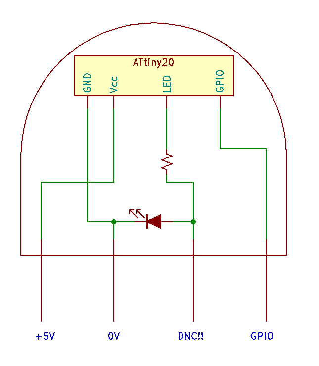
In the feedback, two questions that repeatedly came up were (1) can the LED be reprogrammed? and (2) can the LED respond to inputs? The answer to both questions is no, it can't. Once that LED is freed from its programming board, the program can't be altered. And it's designed to drop-in replace a conventional LED, so an extra I/O pin was never going to happen. But I still had some other ideas....
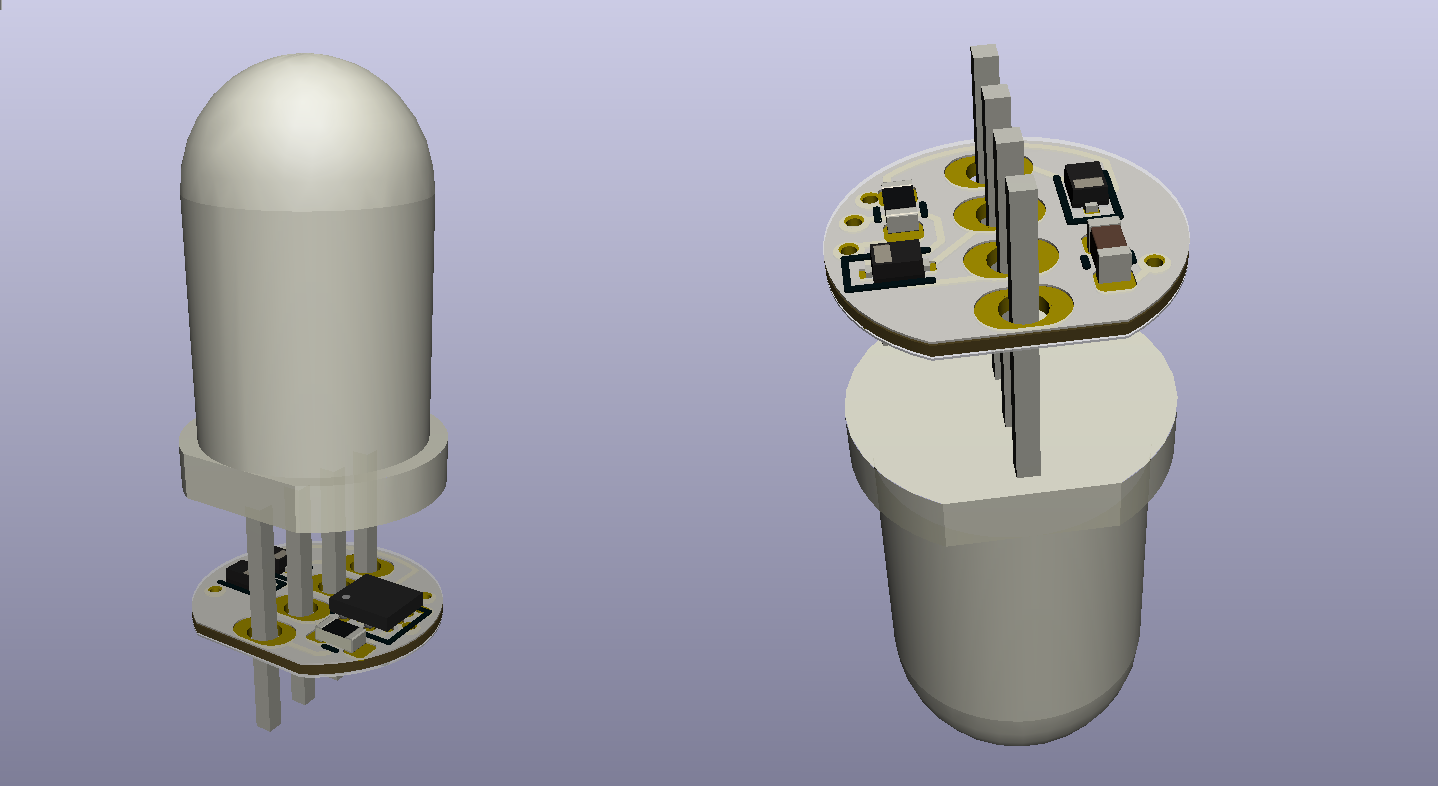
By taking a 5mm through-hole RGB LED and carefully blowing up two of the colors, we can make a PCB with a similar form factor to the previous project, but now it has two extra legs to use for things. Breadboard tests have been super promising! So now it's time to figure out some tough questions:
- What to name this dingus? LEDuino is taken.
- How to explain the function, purpose, and design of the project? You can help by asking me questions, especially if something seems unclear.
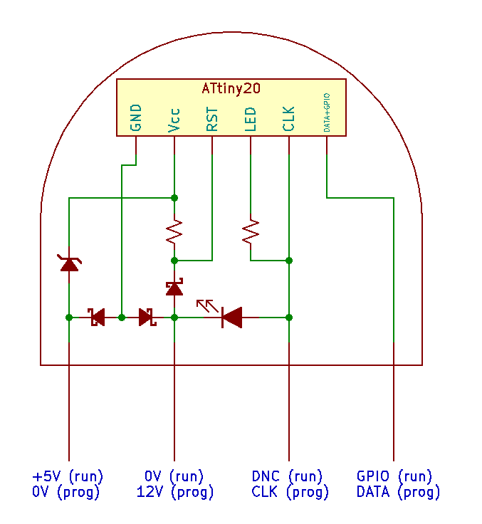
- What to do about the fact that there needs to be a different PCB for each variant? If I want a programmable red LED, I need a different PCB than if I want a programmable blue LED. And if I have common-anode LEDs, or common-cathode LEDs, I'll need different PCBs for those too. This project is not 1 PCB, it's actually like 24 closely-related PCBs in a trenchcoat.
- The LED is reprogrammable, but it's not trivial! I have to make a special programming accessory, too. What features should that have? I don't know. It would be neat to make a lil' LED playground but I'm not clear on what I want it to do, yet.
- How to blow up the LEDs in a consistent fashion? They cannot be allowed to become a short. I'm astonished by how little info I can find on this particular flavor of magic smoke.
- Will it still work as a conventional LED, too? I suppose this is easy enough to test. As [cpldcpu] describes in this neat hack, there is a path for current to flow and possibly turn on the microcontroller even when the microcontroller's Vcc pin is left floating.


 Jens Hauke
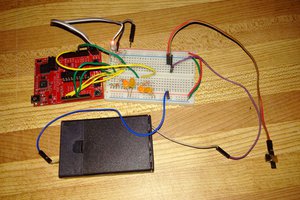
 Petri Varsa
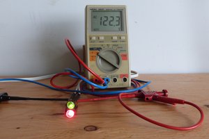
 MagicWolfi
Hello Sam,
In the vein of more pins, you may have a look at addressable through hole 5mm LEDs (search for ADA1938).
They have 4 pins like RGB LEDs too but you don't need to blow up any internal LEDs ;-)
You get to choose all the color you want and still free up 2 pins (the serial input and output)
The schematic will be simpler from the previous TL431 design which can free some space for a pad on which a programming jig could get you all the 5 TPI signals. If I'm not mistaken : power and gnd from the power pins of the LED. Clock and data from the other 2 pins that used to go to serial in and out and finally a pad on the PCB to get the reset signal.
This could also be combined with the power line hack from cpldcpu if in normal operation, you want to change the color or animations and the 2 pins are used.
Just a thought.
Anyway, great project with a lot of hack, I love it!