 Sam Ettinger
I am still cleaning up and preparing things for the git repo, please bear with me in the meantime. So in my last project, I fit an ATtiny20, a shunt IC, and a quartet of 0402 passives onto a disk tucked under a 5mm LED. It existed in parallel with the LED itself. I am fairly sure a similar approach will work here.
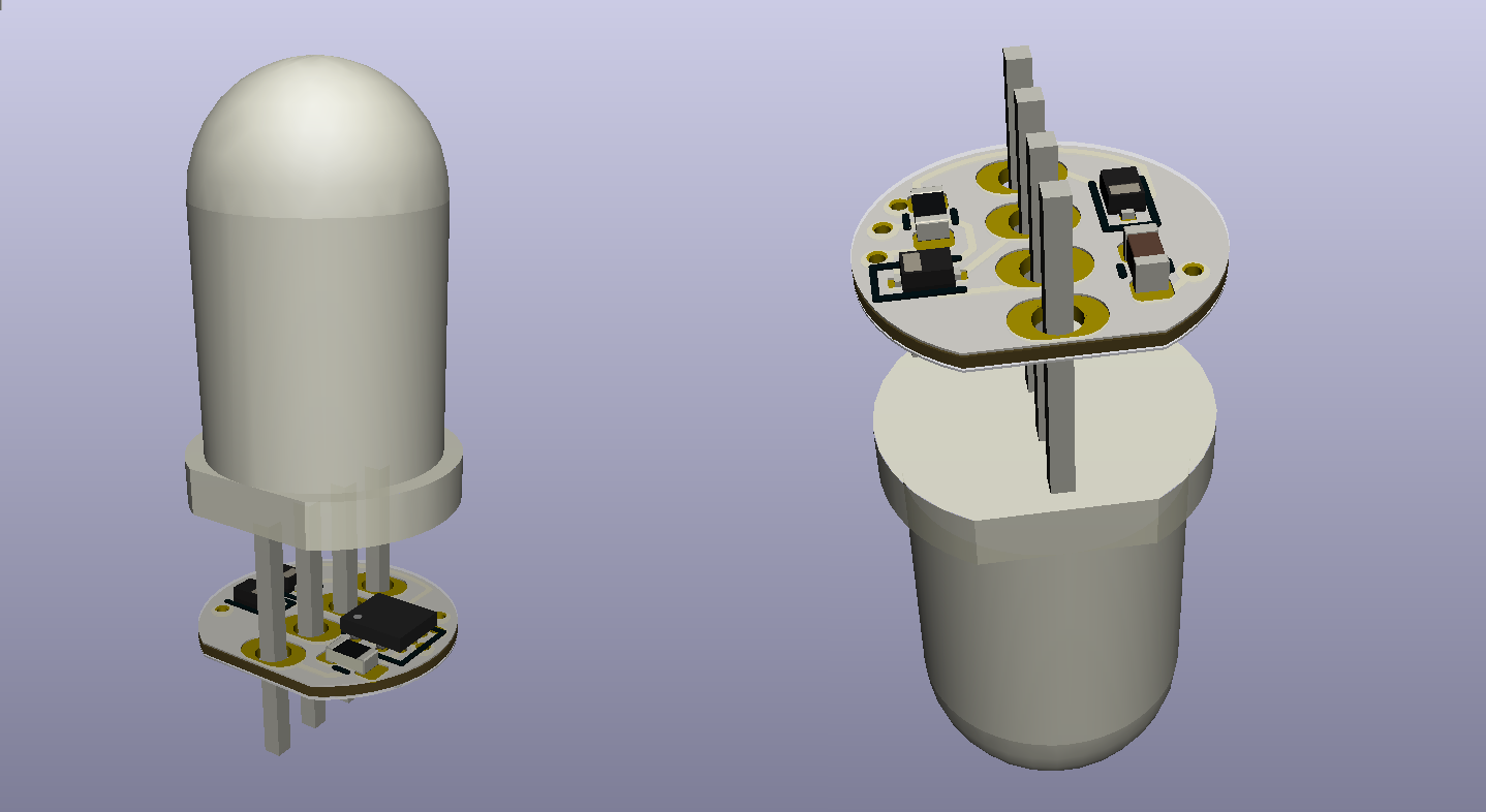
The 4 pads for the LED legs and the one flattened edge makes routing very interesting. There's the left side of the PCB, and the right side of the PCB, and space for just two traces (one on front, one on back) to connect them. I end up tying a lot of unused pins to each other, just so I can route through them more easily. The function of each LED leg changes depending on which parts of the LED are burnt-out or not.
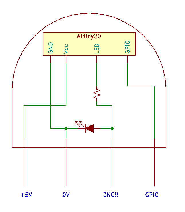
A monochrome LED with 4 pins
I'll need more than two pins if I want to give the ATtiny20 some I/O and make it reprogrammable. 5mm RGB LEDs with 4 pins exist, and they are cheap. If I can blow up 2 of the 3 diodes, that effectively gives me a monochrome LED with four legs to connect to my microcontroller. I like this approach because the legs are securely set in the epoxy lens and should give the finished part some more strength. But it does mean taking existing RGB LEDs and destroying them in a rather specific way that doesn't always work.
Open question #1: How to consistently destroy LEDs without shorting them
To free up the extra legs, I need these diodes to fail and NOT short out. Is there a way to consistently do that? I have been breaking diodes by very briefly zapping them with a 9V battery and no current-limiting resistor. About 85% of the time, this makes the diode fail open, leaving a tiny brown smear in the lens (which I can live with) and a disconnected pin. But the rest of the time, the diode fails short, and any further attempts to zap it cause the ex-diode to glow red and eventually the lens pops. Can I get them to fail open more consistently? If I wanted to, could I get them to fail short more consistently? I found one other person asking similar questions on a well-known Australian electronics forum, and all the replies essentially said "Hey dummy, your diodes won't fail if you use them correctly." Very helpful.
I don't have a large sample size yet, but I feel it's worth remarking that, so far, 0/7 red diodes have failed short, 1/7 green diodes have failed short, and 2/6 blue diodes have failed short.
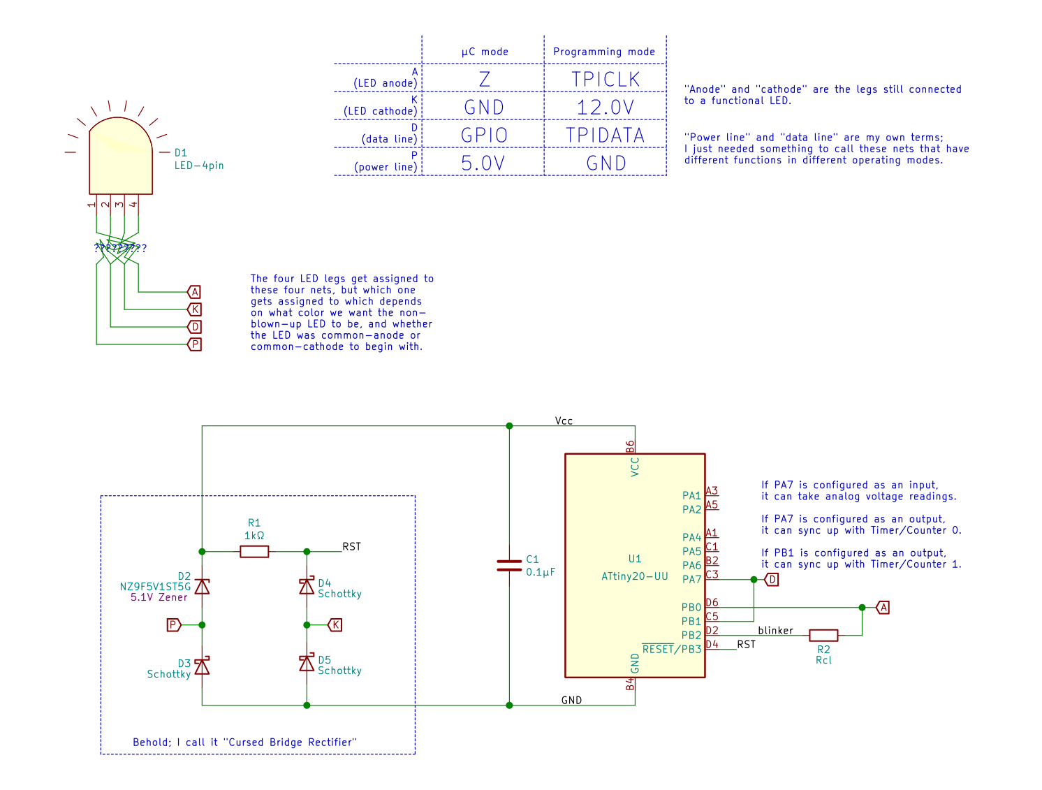
TPI programming with just 4 pins (while still enabling normal operation)
This is a little silly, but bear with me. Normally the Tiny Programming Interface (TPI) requires 5 connections: 5V, 0V, RESET, CLOCK, and DATA. Programming starts when the RESET line is pulled down to 0V and ends when it goes back to 5V. But there's also high-voltage TPI (HVTPI), in which programming starts when the RESET line is pulled up to 12V. In this mode, the RESET mode should never ever drop below 5V, right? So we can get our 5V chip power from the RESET line!

The 5.1V Zener diode is a compact way to get 5V to power the chip. It's worth remarking that a lot of LED datasheets list the absolute maximum reverse breakdown voltage as 5V or so, which would mean 12V on the LED cathode would cause damage. However, that is a very conservative estimate on the LED maker's part; out of all the LEDs I've tested, none have had a reverse breakdown under 30V, so I think we're good. Still, I think it's worth testing each time.
When operating normally, and not in programming mode, these pins need to take different functions. If the LED cathode is at 0V, then we shouldn't directly connect anything to the LED anode, lest it overload the LED. We can still use a spare pin on the microcontroller to toggle the LED, however.
To accommodate both of these functions, some Schottky diodes keep current flowing the right way without too much of a voltage drop:
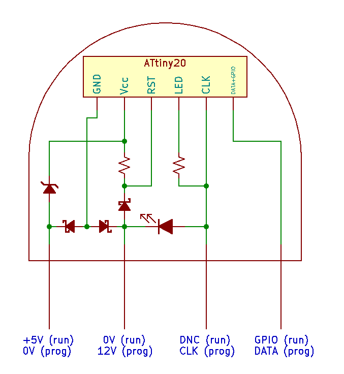
A more formal schematic is below. But note that this is not a complete schematic! I suppose that's obvious from the scramble of wires on D1...
The actual programmer
I have not put enough thought into this part yet. I am envisioning an Arduino UNO size board, posssibly. When you want to program your LED, you put it in the special LED socket for programming, connect the board to your computer (with an on-board USBtinyisp? Or expect the user to own a USBasp? Or something else??), and upload your program. Then, to test the LED, you put it in a different LED socket, perhaps one that nicely interfaces with some knobs and buttons and speakers built into the board. Finally, you can take your programmed LED and solder it someplace or something.
Will the LED still fit in the programmer socket after you've bent and trimmed the legs? I don't know! How will the programmer handle different programmable LED PCBs? For example, a circuit that lights up red and came from a common-cathode LED will probably have its pins arranged like this: anode, cathode, data line, power line. Meanwhile, a circuit that lights up blue and came from a common-anode LED would probably have the pins arranged like this: data line, anode, power line, cathode. There are definitely ways to re-configure a programmer to handle one or more arrangements, but how simple or complex do I make them?
Discussions
Become a Hackaday.io Member
Create an account to leave a comment. Already have an account? Log In.