 looperTwentyThree
The evaporator coil / heater core box was made out of of a combo of PETG and aluminum sheet metal. PETG seemed like a suitable material as it is cheap, relatively easy to print with and is somewhat tolerant of heat. I assumed the heater core would not be in direct contact with the box and the temperature of the air travelling out of the heater core would be cooler than the engine coolant. I have not done any testing to quantify the melting temperature of PETG yet, so there is a gamble there. I figured if the worst case scenario happens where the box starts to melt under the heat, I could throttle back the flow of coolant so the air temperature coming out of the heater core, resulting in less-hot hot air coming out of the heater core.
As far as controls go, my general goal was to have as few moving parts as possible, and to have all the dampers, fans and valves able to be remotely controlled by any device on the CAN-bus network. I chose to use (12) bipolar stepper motors to control the variable air valves at each vent, which allowed me to make the design of the HVAC box smaller and more modular. The stepper motors were cheap and I had a ton of 'em to use up as they were 15 degree/step and had an unconventional mounting/interfacing method. Driving a 2" butterfly valve takes virtually no torque and since precision isn't priority here, these motors seem to fit the application, and there are only a few moving parts to boot.
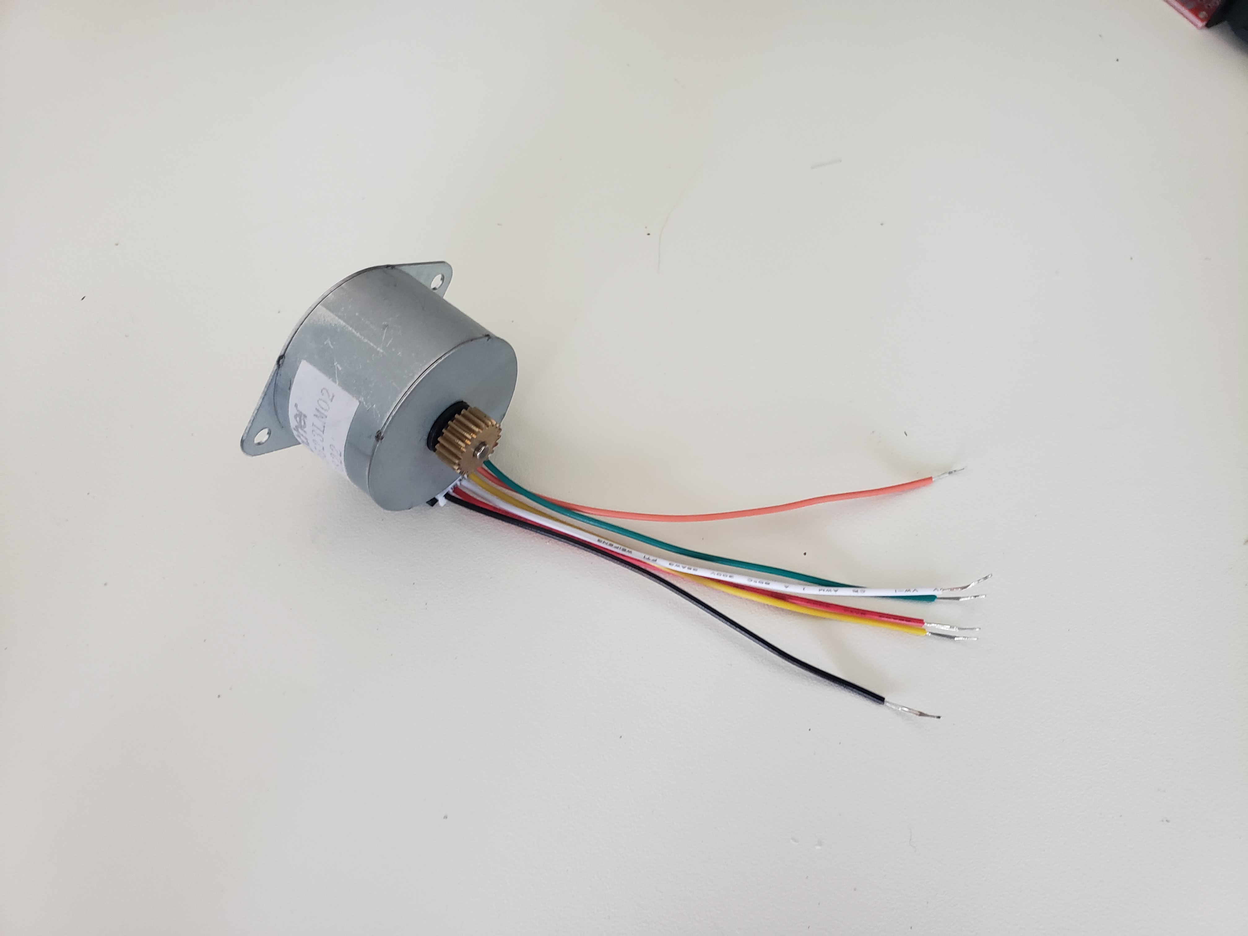
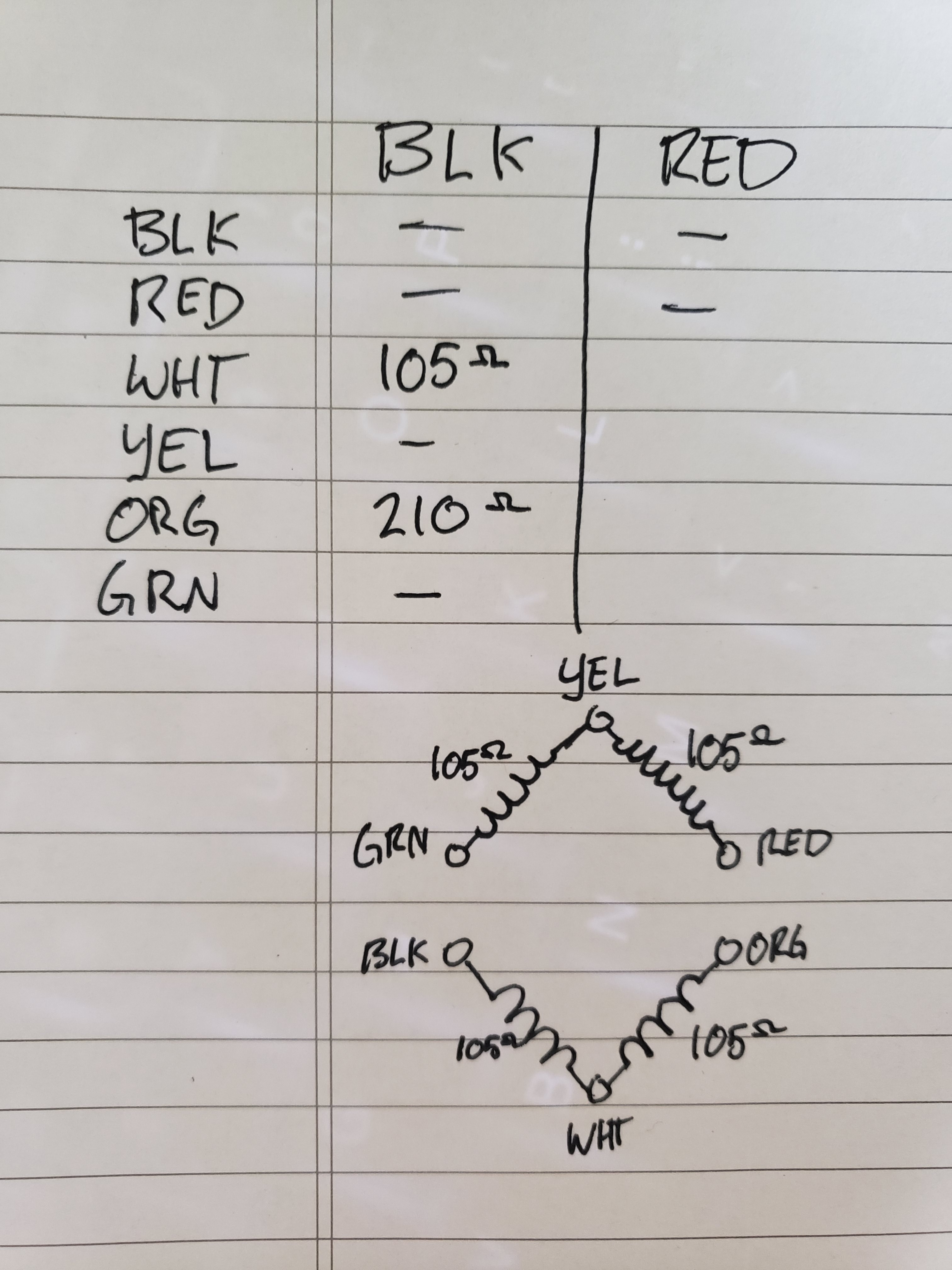
So far it has been impossible to find a datasheet for these motors as they appear to have been built for a unique application. The customer name on the bag identifies as an old (out-of-business) paper mill, which makes sense why I found them in an auction. To find out which pins correspond to each coil, I probed each pin with a multimeter to see how the windings were configured.
Driving each stepper motor is an A9844 stepper motor driver and a micro limit switch for setting initial position on the butterfly valve. To make things compact I soldered the stepper drives to a proto board, added the necessary 100uF capacitors for input voltage protection, and wired the drivers to an Arduino mega2560.
Unlike the original HVAC system this truck was installed with, I wanted to add some "smarts" to the heating/cooling system such as temperature feedback, pressure drop across each component, and relative humidity get some analytics on heat transfer through the system. The amazing thing is that there are very cheap sensors that are readily available to do this sort of thing. I bought a five pack of BMP180 barometric pressure and temperature sensors, two pack of DHT22 humidity and temperature sensors, one SHT31-D humidity and temperature sensor and six TMP36 analog temperature sensors. I2C makes it easy to interface the sensors to the Arduino. Address conflicts caused me to use an I2C multiplexer to interface the digital sensors. I imagine there are several ways to get around the address problem when using an array of I2C devices under the same fixed address, and I would like to know that other people have done.
The original fan control system on this truck allowed for four fan speed settings (OFF-LO-MED-HI) which interfaced the fan by three relays and a resistor network. I wanted to make the system a little simpler by replacing those fan controls with a solid state relay, such as the type found on 3D printer headed beds, and other applications. I wont say this is the best solution, but it sure is cheap and requires only four wires to control the fan with, making for a simple wire install, and a high degree of fan speed resolution.
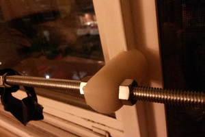
Since I changed the orientation of the heater core and evaporator coil to be inline to each other, I needed a way to control the flow of coolant flowing through the heater core. When the system is in "cooling" mode, the heater core must be cool and not transferring any heat to the cool air passing by. To achieve...
Read more »


 Mild Lee Interested
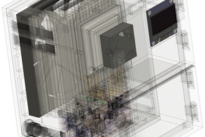
 Jung Hoon Lee
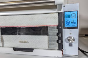
 Xander Skyrien
this is interesting because I have a classic jaguar XJ-S built in 1987 which has the original and at the time state of the art climate control system made by Delanair. It too had blending of cooled and heated air, pwm driven variable speed blowers and servos all controlled by microcontroller. About 20 or more years ago I published online a detailed functional description and fault finding guide. The info has now passed into the public domain classic jaguar community. The electronic design was perfect and utilised lots of sensors. What failed often was water damage and mechanical wear. Also a problem was deterioration of the materials used for the airflow valves.