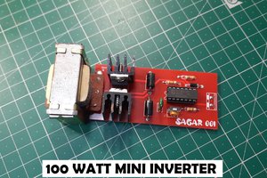
Sagar 001
What if I will say about using a Transformer-less power supply for low power projects. There is no need of any SMPS or PSU. Also it is very easy to make all the data, Gerber files, PCB layouts and circuit diagram are available here. To give a better and professional looks we will use JLCPCB service to build these prototype. Yep, this project is brought to you by JLCPCB offering best quality PCB's (5pcs double layered in just $2). https://jlcpcb.com/SSRF
note** This power supply can only handle low power applications such as data collection, ESP camera and data sharing IOT platforms. And speaking of that capacitor, it’s a safety-critical part of the circuit. It is subjected to continuous high alternating voltages and if it fails short, the “5 V” output is at mains voltage and parts may catch fire. This is a job for an X-rated capacitor. You’ll see them marked X1 or X2 mostly, with X1 being able to withstand higher voltage spikes. Either one will do, just be sure that it’s rated X and specified for your mains voltage level.
Safety first: The one part of a TPS that can hold charge is the reactive capacitor, and that’s why it should have a bleeder resistor across it. In our example circuit, 0.6 μF * 1 MΩ = 0.6 seconds, and you’re probably good waiting at least five of these time constants before touching anything, so count to three
The principle:
A transformer-less power supply (TPS) is basically just a voltage divider that takes the 115 or 220 VAC from your wall and divides it down to whatever voltage you want. If that voltage needs to be DC, it is rectified through a few diodes, and maybe regulated to a maximum voltage but we’ll get to that in a minute.
Normally, DC voltage dividers are made with a pair of resistors. Combined, they define the current flowing through the path, and the top resistor can then be chosen to drop the difference between the input voltage and the desired output. If, in our case, that difference is some one or two hundred volts, even if it only has to pass a few tens of milliamps, that resistor is going to get hot fast.

After the capacitor, the AC that passes through needs to be rectified into DC. A normal half- or full-wave rectifier will work here: a handful of diodes and a large-valued smoothing capacitor. If the load isn’t constant, you’ll probably want to limit the maximum voltage seen by the capacitor with a Zener diode, so that excess current is shunted to ground when the load draws less than the 25 milliamps we designed for. These parts only see low voltages, so there are no special requirements here. Also, more the number of capacitors, more will be the output current through out.
Finally, note that there are many possible configurations of this circuit. Instead of dropping most of the voltage between live and our device, it’s also possible to connect our device straight to the live wire, with the capacitor in the lower leg of the voltage divider — the same circuit upside-down. The fuse and safety resistors can be located anywhere in the circuit, of course. But the basics are the same: the capacitor acts as one leg in a voltage divider, followed by some rectification and regulation, with the load as the other leg.
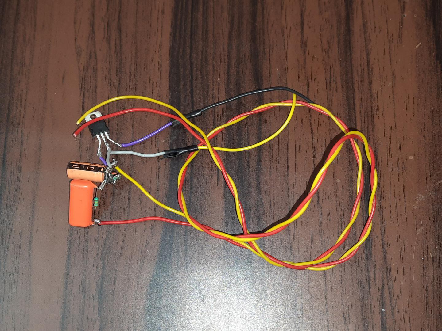
Components required:
1) 105/104/474K capacitor
2) 1Mohm,100ohm/10k resistor
3) 1N4007 Diodes
4) Preferred Zener diode (5v to 18v)
5) 220uF/470uF electrolytic capacitor
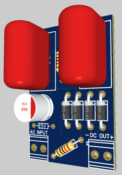
Circuit diagram:
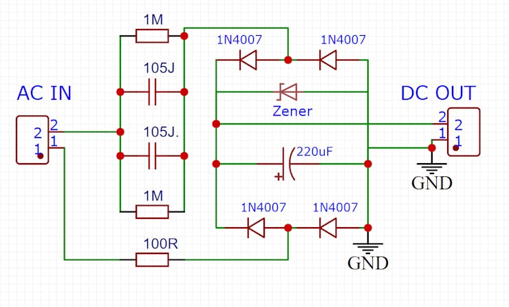
Circuit description:
AC supply from the 1st connector is supplied to capacitor and diodes with 100ohm resistor. This 100ohm resistance is acts like a fuse for the circuit, and protect from over voltage and current issues. There is always a resistor in parallel with capacitors, so it can discharge the circuit when not in use. A full bridge rectifier with electrolytic capacitor as a filter to supply dc output. Zener in the circuit is to regulate the power, gives a proper stable dc to the circuit.

 Adam Redfern
 w_k_fay
 Lithium ION